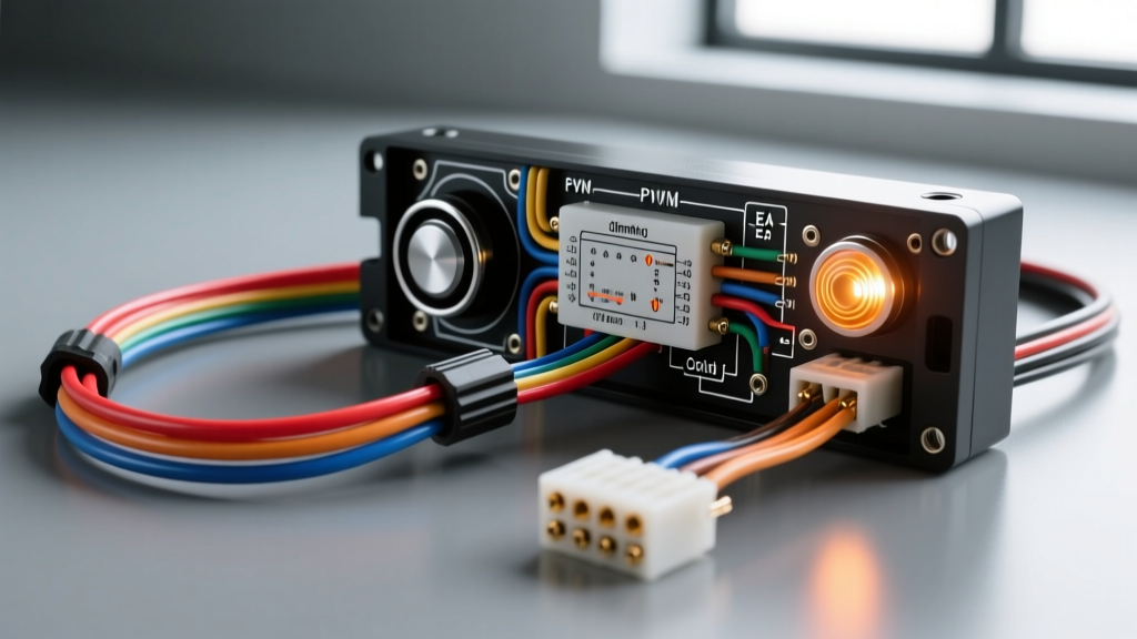
Introduction to Automotive Audio Lamp Circuits
Integrating an aftermarket head unit or amplifier requires a precise understanding of the vehicle's lighting and status circuits. The lamp wiring diagram for car audio applications primarily governs two distinct systems: the head unit illumination (dash backlight) circuit and the amplifier indicator/status lamp circuit. Miswiring these low-current circuits can trigger Body Control Module (BCM) faults, blow micro-fuses, or result in erratic dimming behavior. This technical specification reference details the EIA/CEA standard color codes, Pulse Width Modulation (PWM) dimming parameters, and OEM integration requirements for automotive audio lamp circuits.
Standard EIA/CEA Head Unit Illumination Pinouts
The Consumer Technology Association (CTA), formerly the CEA, established standardized wiring color codes to ensure interoperability between aftermarket head units and vehicle harnesses. When reviewing a standard lamp wiring diagram for a single-DIN or double-DIN receiver, the illumination circuit relies on specific 18 AWG conductors. According to the CTA-2006 Mobile Audio Power Standard, these wires are designed to handle low-current signaling rather than high-amperage power delivery.
| Wire Color | Function | Signal Type | Max Current Draw |
|---|---|---|---|
| Orange | Illumination (+12V Trigger) | Discrete DC Voltage | 500mA (Typical) |
| Orange/White Stripe | Illumination Dimmer | Variable DC or PWM | 100mA - 300mA |
| Brown/White Stripe | Telephone Mute / Dash Lamp Override | Discrete Ground Trigger | 50mA |
The Orange wire is typically tied to the vehicle's headlight switch. When the parking or headlights are engaged, this wire receives +12V, signaling the head unit to switch from daytime to nighttime display mode. The Orange/White wire dictates the actual brightness level of the LCD or button backlighting.
OEM Dash Lamp Circuit Specifications & BCM Integration
Modern vehicles (2010 and newer) rarely use simple rheostats or variable resistors for dash lamp dimming. Instead, the BCM utilizes Pulse Width Modulation (PWM) or multiplexed LIN/CAN bus signals to control interior lighting. Connecting a standard aftermarket stereo's orange/white dimmer wire directly to a GM GMLAN or Ford CAN-bus PWM dimming circuit without proper interfacing can cause severe electrical issues.
The PWM Dimming Conflict
Aftermarket head units typically expect a variable DC voltage (0V to 12V) on the dimmer wire, utilizing an internal RC filter capacitor to smooth the signal. However, OEM PWM circuits operate at high frequencies (typically 200Hz to 1kHz). When the head unit's capacitor attempts to charge during the PWM 'ON' pulse, it draws a massive inrush current. The BCM interprets this as a short circuit, triggering a diagnostic trouble code (DTC) such as U0140 (Lost Communication with BCM) or shutting down the interior lighting bus entirely.
OEM Dimming Protocol Specifications
| Manufacturer | Dimming Protocol | Frequency / Voltage | Required Interface / Fix |
|---|---|---|---|
| General Motors (GMLAN) | Class 2 / GMLAN PWM | ~400Hz, 0-12V Duty Cycle | 1/4W 2.2kΩ Pull-Down Resistor or PAC RP4-GM41 |
| Ford / Lincoln (CAN-bus) | SCP / CAN-bus Multiplex | Digital Data Packet | Axxess XSVI-FORD or Maestro RR Module |
| Chrysler / Dodge (LIN Bus) | Local Interconnect Network | 19.2 kbps LIN Signal | Crutchfield Maestrp or iDatalink Maestro |
| Toyota / Honda (Legacy) | Variable DC Voltage | 0V (Bright) to 12V (Dim) | Direct Splice (No Interface Required) |
For GM applications where a dedicated interface module is not used, installing a 2.2kΩ to 4.7kΩ (1/4 Watt) resistor between the Orange/White wire and chassis ground will limit the inrush current, preventing BCM faults while allowing the head unit's internal filter to read the PWM duty cycle as a proportional DC voltage.
Amplifier Indicator and Status Lamp Wiring
While head unit illumination integrates with the vehicle's dash, the amplifier indicator lamp circuit is an isolated, low-voltage system designed to provide remote status feedback. High-power amplifiers (especially Class D monoblocks and multi-channel marine amps) often feature a 3.5mm jack or a 2-pin/3-pin Molex connector for an external remote LED indicator.
Remote LED Pinout Configurations
When wiring an external status lamp to the trunk, cargo area, or cabin, you must adhere to the manufacturer's specific pinout to avoid damaging the amplifier's internal logic board.
- 2-Pin JST/Molex: Pin 1 is Status Signal (+3.3V or +5V logic high when faulted), Pin 2 is Chassis Ground. Uses a standard bi-color LED or single-color LED with an internal current-limiting resistor.
- 3-Pin Connector (RGB Status): Pin 1 is Power (Red/Green), Pin 2 is Ground, Pin 3 is Protect (Red). Allows the remote LED to glow Green during normal operation and switch to Red during thermal or short-circuit protection events.
Because these are logic-level signals, the wire gauge for remote indicator lamps should be 22 AWG to 24 AWG. Using thicker wire (like 18 AWG) is unnecessary and makes routing through tight grommets difficult. Ensure the external LED assembly includes a built-in current-limiting resistor (typically 330Ω to 470Ω) to prevent drawing more than 10-15mA from the amplifier's logic IC.
Wire Gauge, Insulation, and Connector Specifications
When extending or repairing illumination and indicator lamp circuits, the wire must meet strict automotive environmental standards. According to the SAE J1128 Low Tension Primary Cable Standard, wiring routed behind dashboards and inside door panels must withstand high ambient temperatures and chemical exposure.
| Specification | Illumination / Dimmer (18 AWG) | Remote Amp LED (22 AWG) |
|---|---|---|
| Insulation Type | GXL or TXL (Cross-linked Polyethylene) | PVC or Teflon (PTFE) |
| Temperature Rating | 125°C (GXL) / 150°C (TXL) | 105°C (Standard PVC) |
| Stranding | Multi-strand (16/30 AWG bare copper) | 7/30 AWG tinned copper |
| Connector Type | Metra 72-1761 / Molex MX150 | 3.5mm TRS Jack / JST-SM |
Never use standard household THHN solid-core wire for automotive lamp circuits. Solid-core wire will fatigue and snap under the constant vibration of the vehicle chassis. Always use tinned, multi-strand copper wire with GXL insulation, and seal all splices with dual-wall heat shrink tubing containing an adhesive lining to prevent moisture intrusion and galvanic corrosion.
Troubleshooting Decision Tree: Lamp Circuit Failures
When an illumination or indicator lamp circuit fails, systematic diagnosis is required to isolate the fault. Use the following decision tree to troubleshoot common lamp wiring diagram integration failures.
- Symptom: Head unit display does not dim when headlights are turned on.
Cause: Orange/White (Dimmer) wire left disconnected, or connected to a constant 12V source instead of the OEM dimmer circuit.
Fix: Locate the OEM dimmer wire using a vehicle-specific Crutchfield Car Stereo Wiring Guide and verify the voltage drops or PWM duty cycle changes when the dashboard dimmer switch is adjusted. - Symptom: Dashboard interior lights flicker or BCM throws a U-code after stereo installation.
Cause: The aftermarket head unit's internal filter capacitor is drawing excessive inrush current from the OEM PWM dimming bus.
Fix: Install a 2.2kΩ 1/4W resistor between the head unit's Orange/White wire and chassis ground to limit current draw, or install a dedicated CAN-bus interface module. - Symptom: Amplifier remote LED is completely dead, but amp functions normally.
Cause: Logic ground (Pin 2) is floating, or the 3.5mm jack is not fully seated due to a thick carpet pad.
Fix: Check continuity between the remote LED ground ring and the amplifier chassis. Ensure the 3.5mm plug is clicked fully into the 'REM' or 'STATUS' port. - Symptom: Remote LED glows dimly and turns red intermittently.
Cause: Voltage drop across the 22 AWG remote wire due to an excessively long run (over 15 feet) or a corroded ground connection at the LED housing.
Fix: Clean the ground termination point to bare metal, apply dielectric grease, and verify the logic signal at the amp output reads a clean +3.3V to +5V.
Summary
Proper execution of a car audio lamp wiring diagram extends far beyond simply connecting an orange wire to a headlight switch. Modern automotive electrical systems require installers to understand PWM frequencies, BCM current limits, and logic-level signaling. By adhering to SAE J1128 wire specifications, utilizing proper pull-down resistors for PWM circuits, and respecting the low-current nature of amplifier status LEDs, you can ensure a seamless, fault-free integration of aftermarket audio equipment into complex OEM lighting networks.