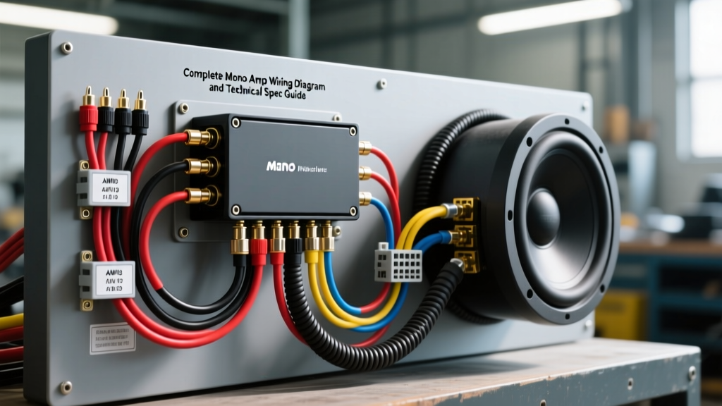
Class D Monoblock Architecture and Efficiency
When consulting a mono amp wiring diagram, it is critical to understand the underlying architecture of the amplifier. Modern monoblock amplifiers utilize Class D (switching) topology. Unlike Class AB amplifiers that operate linearly and dissipate significant heat, Class D amplifiers use Pulse Width Modulation (PWM) to switch output transistors fully on and off at high frequencies (typically 300kHz to 500kHz). This yields efficiency ratings between 80% and 92%.
Because of this high efficiency, the thermal management requirements are reduced, but the instantaneous current draw from the vehicle's electrical system remains massive during heavy bass transients. Therefore, the power and ground wiring specifications must be calculated based on peak current demand and voltage drop limitations, not just continuous thermal limits. According to SAE J1128 standards for low-tension primary cable, voltage drop over distance is the primary limiting factor in DC automotive circuits, making Oxygen-Free Copper (OFC) vastly superior to Copper-Clad Aluminum (CCA) for high-current monoblock applications.
Primary Power, Ground, and Fuse Specifications
The power wire routing from the battery to the amplifier must minimize resistance. The ground wire should be as short as possible, terminating to bare, unpainted chassis metal. Below is the technical specification chart for sizing your primary power and ground conductors based on the amplifier's total RMS wattage output.
| Amp RMS Output | Wire Gauge (OFC) | Max Fuse Rating (Battery) | Max Ground Length | Terminal Type |
|---|---|---|---|---|
| 300W - 500W | 8 AWG | 60A (MIDI/Mini-ANL) | 18 inches | #8 Ring / Set Screw |
| 600W - 1000W | 4 AWG | 120A (ANL) | 24 inches | #4 Ring / Set Screw |
| 1200W - 2000W | 1/0 AWG | 200A (ANL) | 24 inches | 1/0 Ring / Distribution |
| 2500W+ | 2/0 AWG or Dual 1/0 | 300A+ (Class T / ANL) | 12 inches | 2/0 Lugged Busbar |
Note: Fuse ratings at the battery must protect the wire, not the amplifier. Always size the fuse according to the ampacity of the wire gauge used, referencing the SAE J1128 ampacity charts.
Signal Input and Remote Turn-On Pinouts
Monoblock amplifiers require specific signal inputs to trigger the PWM controller. While many installations use standard RCA cables, understanding the pinout and voltage thresholds is vital for OEM integration and noise rejection.
RCA Low-Level Inputs
- Signal Voltage: Typically accepts 200mV to 4V (some modern amps accept up to 8V to prevent clipping from high-output DSPs).
- Shielding: Use twisted-pair, shielded RCA cables. The shield must be grounded at the source unit (head unit or DSP) only, to prevent ground loop alternator whine.
High-Level (Speaker Level) Inputs
When integrating with factory amplifiers, you will use the high-level input harness. Modern Class D mono amps feature differential high-level inputs that reject common-mode noise.
- Pin 1 (Left +): Connects to OEM front left positive speaker wire.
- Pin 2 (Left -): Connects to OEM front left negative speaker wire.
- Pin 3 (Right +): Connects to OEM front right positive speaker wire.
- Pin 4 (Right -): Connects to OEM front right negative speaker wire.
- DC Offset Detection: Many amps use the DC offset present on OEM BTL (Bridged-Tied Load) speaker outputs to trigger the remote turn-on circuit automatically.
Remote Turn-On (REM) Terminal
The REM terminal requires a +12V DC signal to close the internal relay and activate the power supply. Use 18 AWG primary wire. The voltage threshold to trigger the circuit is typically 9V to 15V DC. If your head unit lacks a dedicated remote output, a PAC TRUNK-LOC or a simple relay triggered by the accessory (ACC) circuit in the fuse box is required.
Subwoofer Impedance Load Wiring Diagrams
Matching the subwoofer's final impedance to the amplifier's stable load rating is the most critical step in the mono amp wiring diagram process. Mismatching impedance will either halve your power output (too high) or trigger the amplifier's over-current protection and potentially destroy the output stage (too low).
Diagram A: Dual 4-Ohm DVC Subwoofer Wired to 1-Ohm (Parallel)
This configuration is used for high-output 1-ohm stable monoblocks (e.g., JL Audio HD1200/1, Rockford Fosgate T1500-1bdCP).
- Step 1: Connect Sub 1 Voice Coil A (+) to Sub 1 Voice Coil B (+).
- Step 2: Connect Sub 1 Voice Coil A (-) to Sub 1 Voice Coil B (-).
- Step 3: Run a jumper wire from Sub 1 (+) terminals to Sub 2 (+) terminals.
- Step 4: Run a jumper wire from Sub 1 (-) terminals to Sub 2 (-) terminals.
- Step 5: Connect the amplifier's positive speaker terminal to the combined (+) node, and the negative terminal to the combined (-) node.
- Math: (4Ω || 4Ω) = 2Ω per sub. Two 2Ω subs in parallel = 1-Ohm Final Load.
Diagram B: Dual 2-Ohm DVC Subwoofer Wired to 2-Ohm (Series-Parallel)
This is the safest and most common configuration for standard Class D monoblocks, maximizing power while keeping current draw manageable.
- Step 1 (Series per Sub): Connect Sub 1 Voice Coil A (+) to the Amplifier Positive (+).
- Step 2: Connect Sub 1 Voice Coil A (-) to Sub 1 Voice Coil B (+).
- Step 3: Connect Sub 1 Voice Coil B (-) to Sub 2 Voice Coil A (-).
- Step 4: Connect Sub 2 Voice Coil A (+) to Sub 2 Voice Coil B (+).
- Step 5: Connect Sub 2 Voice Coil B (-) to the Amplifier Negative (-).
- Math: Voice coils in series = 4Ω per sub. Two 4Ω subs in parallel = 2-Ohm Final Load.
For comprehensive impedance matrices and specific model compatibility, refer to the JL Audio Engineering Support subwoofer wiring calculator.
Terminal Hardware and Torque Specifications
A common failure point in mobile audio is the physical termination of the wire at the amplifier's set-screw terminals. Stranded OFC wire will compress and deform over time due to thermal cycling and vehicle vibration, leading to a loose connection, arcing, and melted terminal blocks.
- Preparation: Strip exactly 1/2 inch of insulation. Do not tin (solder) the wire ends before inserting them into set-screw terminals. Solder is soft and will creep under the pressure of the set screw, causing a loose connection. Instead, use a closed-end ferrule or a stamped ring terminal crimped with a hex-crimp die.
- Torque Specs: Most aftermarket amplifier set screws require between 2.0 Nm and 3.5 Nm of torque. Use a calibrated inch-pound torque screwdriver to ensure the wire is clamped securely without stripping the brass or zinc-alloy terminal block threads.
- Anti-Oxidant: Apply a small amount of NO-OX-ID A-Special or dielectric grease to the exposed copper before termination to prevent galvanic corrosion, especially in humid climates or trunk installations.
Electrical System and Alternator Sizing
A mono amp wiring diagram is incomplete without accounting for the vehicle's charging system. To determine if your factory alternator can support the amplifier, use the following formula to calculate peak amperage draw:
Total Amperage = (Total RMS Wattage / Amplifier Efficiency) / 13.8V (Alternator Output)
Example Calculation:
You are installing a 1200W RMS monoblock with an 80% efficiency rating.
1200W / 0.80 = 1500W (Total Power Consumed)
1500W / 13.8V = 108.6 Amps
If your vehicle has a 130A alternator, and the vehicle's baseline electrical load (ECU, fuel pump, HVAC, lights) consumes 50A, you only have 80A of reserve capacity. This 108A draw will cause voltage to drop below 12.0V, triggering the amplifier's under-voltage protection and causing the headlights to dim. Upgrading to a high-output alternator (e.g., Mechman 250A) and adding a 2.0 Farad carbon-fiber capacitor or a lithium-ion auxiliary battery is required for sustained high-SPL output. For more on vehicle electrical baselines, consult the Crutchfield Car Audio Wiring Guide.
Troubleshooting Protection Mode Triggers
If your monoblock amplifier enters protection mode immediately upon receiving the remote turn-on signal, use this decision tree to isolate the fault:
- Disconnect all speaker wires and RCA cables. Turn the amp on. If it powers up normally (green/blue LED), the fault is in the speaker wiring or signal input.
- Check Speaker Impedance. Use a digital multimeter (DMM) to measure the DC resistance at the amplifier's speaker terminals. It should read roughly 20% lower than the nominal AC impedance (e.g., a 2-ohm load will read ~1.6 ohms DC). If it reads 0.0 ohms, you have a shorted voice coil or a pinched speaker wire grounding to the chassis.
- Check Voltage at Terminals. With the vehicle running, measure DC voltage directly at the amplifier's B+ and GND set screws. If it reads below 11.5V, you have excessive voltage drop in the power wire or a failing alternator. If it reads above 15.5V, your vehicle's voltage regulator is failing.