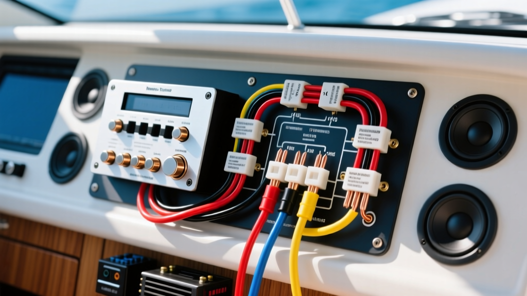
Introduction to Marine Audio Upgrades
Upgrading a boat's stereo system from an outdated CD receiver to a modern digital media player with Bluetooth requires a fundamental understanding of marine electrical environments. Unlike automotive applications, a marine stereo wiring diagram must account for saltwater exposure, high humidity, UV degradation, and constant vibration. This guide provides a comprehensive, ABYC-compliant approach to wiring aftermarket marine head units (such as Fusion, Clarion, and Boss Audio), ensuring reliable performance and preventing catastrophic electrical fires or black-wire corrosion.
Understanding the Marine Stereo Wiring Diagram
Most aftermarket marine head units utilize a standard 16-pin ISO harness or a proprietary waterproof Molex connector. While the color codes largely mirror standard automotive 12V DC systems, the execution and materials required for a marine environment are vastly different. Below is the standard pinout and wire color configuration for a typical marine stereo upgrade.
| Wire Color | Function | Recommended AWG | Marine-Specific Notes |
|---|---|---|---|
| Yellow | Constant 12V (Memory) | 14 AWG | Connect directly to the positive DC busbar. Maintains presets and clock. |
| Red | Switched 12V (Accessory) | 14 AWG | Connect to the load side of a dedicated helm rocker switch. |
| Black | Chassis / System Ground | 14 AWG | Must terminate at a negative DC busbar, never to the engine block or hull. |
| Blue | Power Antenna / Amp Turn-On | 18 AWG | Triggers external marine amplifiers. Use a relay if powering multiple amps. |
| White / Gray | Front L/R Speakers (+/-) | 16 AWG | Minimum gauge for in-dash or coaming runs. |
| Green / Purple | Rear L/R Speakers (+/-) | 16 AWG | Upgrade to 12 AWG if routing to a wakeboard tower. |
ABYC E-11 Compliance & Wire Selection
When executing a marine stereo wiring diagram, wire selection is non-negotiable. The American Boat & Yacht Council (ABYC) E-11 Standard mandates the use of stranded, tinned copper wire for all marine DC electrical systems. Untinned copper wire reacts with salt air and moisture, creating copper oxide—a black, powdery substance that drastically increases electrical resistance and causes voltage drop. This phenomenon, known as 'black wire disease,' will cause your head unit to reboot at high volumes or fail to power on entirely.
Why Tinned Copper is Mandatory
Marine-grade 14 AWG wire features individual copper strands that are individually coated in tin before being bundled and insulated with a moisture-resistant PVC or XLPE jacket. This tin coating prevents oxidation from creeping under the insulation. Always verify that your wire spool is explicitly labeled 'Marine Grade' or 'Tinned Copper' (UL 1426 / SAE J1128).
Power Distribution & The Ignition Bypass
In a car, the Red (Accessory) wire connects to the ignition switch's ACC position. Boats, however, rarely feature an 'Accessory' key position. The main ignition switch typically feeds the starter and ignition systems directly. To properly wire the Red switched wire in a boat, you must integrate a dedicated toggle or rocker switch on the helm panel.
Wiring the Helm Rocker Switch
- Source Power: Run a 14 AWG tinned wire from a fused port on your main negative/positive DC distribution panel to the helm.
- Switch Integration: Connect this source wire to Pin 2 (Line In) of a Carling V-Series marine rocker switch.
- Load Output: Connect Pin 3 (Load Out) of the rocker switch to the Red wire of your marine stereo harness.
- Illumination: Connect Pin 7 (Ground for LED) to the negative busbar, and Pin 6 (12V for LED) to a navigation light circuit so the switch illuminates only at night.
Expert Note: Never wire both the Yellow and Red wires to the same constant 12V source. This will allow the stereo to remain on when the boat is unattended, leading to parasitic draw and a dead starting battery.
Speaker Wire Routing & Tower Upgrades
Routing speaker wire through a boat's hull and up a wakeboard tower introduces significant distance. Standard 16 AWG speaker wire is sufficient for runs under 10 feet (such as bow or cockpit speakers). However, routing wire up an aluminum or fiberglass tower to marine tower speakers often exceeds 20 feet round-trip.
Calculating Voltage Drop for Tower Speakers
Long wire runs increase resistance, which degrades the amplifier's damping factor and results in muddy, distorted bass response at high volumes. For tower speaker runs exceeding 15 feet, upgrade to 12 AWG marine-grade speaker wire. Furthermore, when drilling through aluminum towers, always use rubber grommets to prevent the sharp metal edges from slicing the wire insulation, which would cause a short circuit against the grounded tower frame.
Termination & Corrosion Protocols
The most common point of failure in any marine stereo wiring diagram is the termination point. According to Marine How To and ABYC guidelines, soldering is prohibited as the sole means of mechanical connection. Solder joints are brittle and will crack under the constant vibration of a boat hull slamming against wakes.
The Proper Crimp and Seal Method
- Strip the wire using a precision wire stripper to avoid nicking the tinned strands.
- Slide a piece of 3:1 adhesive-lined marine heat shrink over the wire.
- Use a ratcheting crimp tool to compress a tinned, nylon-insulated ring terminal onto the wire. The ratchet ensures the exact compression required for a gas-tight connection.
- Slide the adhesive-lined heat shrink over the terminal barrel and apply heat with a heat gun (never an open flame lighter). The inner adhesive will melt and seal the connection, completely blocking moisture ingress.
Amplifier Integration & RCA Routing
When adding a marine subwoofer amplifier, you must run RCA interconnect cables from the head unit to the amp. In a boat, alternator whine is a frequent issue caused by electromagnetic interference (EMI). To prevent this, route your RCA cables on the opposite side of the boat's central wire chase, maintaining at least an 18-inch separation from the 12V DC power cables and the engine wiring harness. Use marine-grade RG-174 coaxial RCA cables with corrosion-resistant gold-plated or nickel-plated connectors.
For the amplifier's main power, use 4 AWG or 8 AWG tinned marine wire (depending on total wattage), and protect it with an MRBF (Marine Rated Battery Fuse) installed within 7 inches of the positive battery terminal, as mandated by Blue Sea Systems circuit protection guidelines.
Troubleshooting Common Marine Stereo Failures
- Symptom: Stereo loses presets and clock when the boat key is turned off.
Cause: The Yellow (Constant) and Red (Switched) wires are swapped, or both are wired to the helm rocker switch.
Fix: Verify the wiring diagram. Rewire the Yellow wire directly to the unswitched positive DC busbar, and ensure the Red wire is on the load side of the switch. - Symptom: High-pitched whining noise in the speakers that changes pitch with engine RPM.
Cause: Ground loop or RCA cables running parallel to power wires.
Fix: Ensure the head unit and the amplifier share a common grounding point on the same negative busbar. Separate RCA and power wiring. - Symptom: Head unit shuts off or reboots when bass hits hard.
Cause: Voltage drop due to undersized power/ground wires or a loose, corroded crimp connection.
Fix: Check the 14 AWG power and ground wires. Re-crimp terminals using adhesive heat shrink and verify the inline ATC blade fuse is clean and tightly seated.