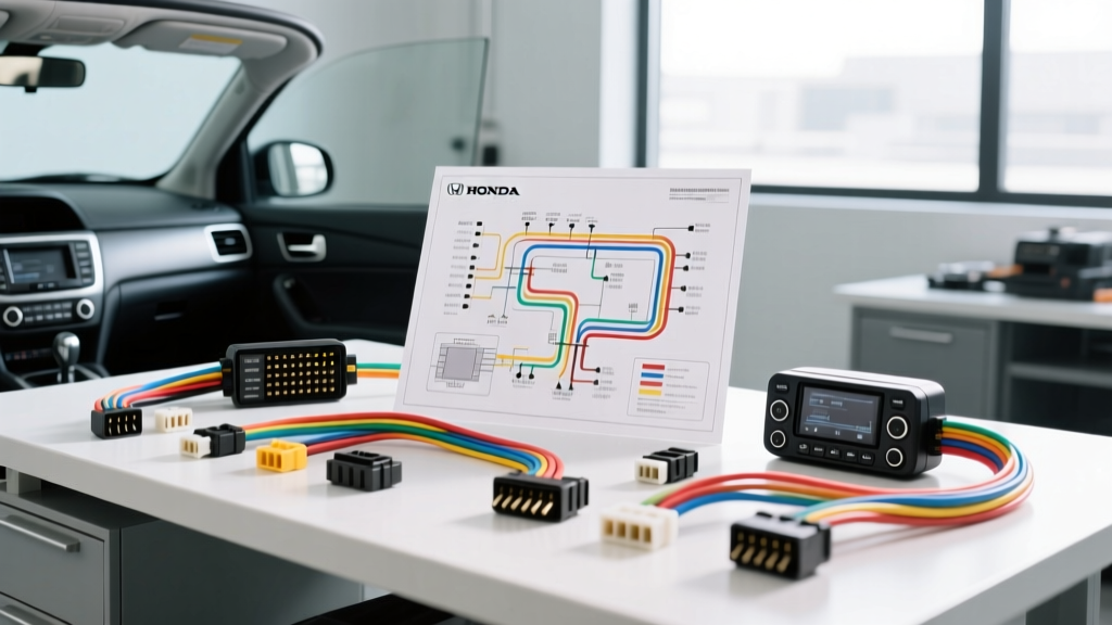
Upgrading the Honda Element: Beyond the Basic Wiring Diagram
Upgrading the stereo in a 2003-2011 Honda Element requires a solid understanding of the factory electrical architecture. Unlike older vehicles that relied on simple analog 12V triggers, the Element integrates its audio system with the vehicle's Multiplex Integrated Control Unit (MICU). This means referencing an accurate Honda Element radio wiring diagram is only the first step; selecting the correct aftermarket wiring harness product is critical to avoid parasitic battery drains, loss of steering wheel controls, and blown factory amplifiers.
In this comprehensive product comparison and selection guide, we break down the exact OEM pinouts, compare the top aftermarket harness solutions from Metra, Axxess, and PAC, and provide expert installation specifications to ensure your audio upgrade is seamless, safe, and reliable. Whether you are driving a base model DX or a fully loaded EX with the factory subwoofer, choosing the right integration product is just as important as the head unit itself.
The Core Honda Element Radio Wiring Diagram (24-Pin OEM)
From 2003 to 2011, the non-amplified Honda Element utilizes a standard 24-pin gray connector. However, the presence of a factory subwoofer (found in 2007-2011 EX trims) introduces an external amplifier and a secondary harness. Below is the foundational pinout for the primary 24-pin chassis connector. Always verify your specific trim level against Honda TechInfo service manuals before cutting any factory wires.
| Pin | Wire Color | Function | Aftermarket EIA Equivalent |
|---|---|---|---|
| 1 | Green | Front Left Speaker (+) | White |
| 2 | Green/Black | Front Left Speaker (-) | White/Black |
| 3 | Gray | Front Right Speaker (+) | Gray |
| 4 | Gray/Black | Front Right Speaker (-) | Gray/Black |
| 5 | Blue | Rear Left Speaker (+) | Green |
| 6 | Blue/Black | Rear Left Speaker (-) | Green/Black |
| 7 | Purple | Rear Right Speaker (+) | Purple |
| 8 | Purple/Black | Rear Right Speaker (-) | Purple/Black |
| 9 | Red/Black | Illumination / Dimmer | Orange/White |
| 10 | Yellow/Red | 12V Accessory (Ignition) | Red |
| 14 | Black | Chassis Ground | Black |
| 15 | White/Red | 12V Constant (Battery) | Yellow |
| 16 | Light Green | Steering Wheel Control (SWC 1) | N/A (Requires Module) |
| 17 | Light Green/Black | Steering Wheel Control (SWC 2) | N/A (Requires Module) |
| 24 | White | CAN-Bus / MICU Data | DO NOT CONNECT |
The Multiplex CAN-Bus Trap (Pin 24)
Pin 24 (White wire) is the most critical wire in the Honda Element radio wiring diagram. It connects to the MICU for data communication. If you use a cheap, unshielded universal harness or accidentally bridge 12V power to this pin during installation, the MICU will remain "awake" after the key is removed. This results in a parasitic draw of 300mA to 500mA, which will completely drain your battery within 48 hours. Premium harnesses physically omit this pin from the plastic molding to prevent accidental contact.
Product Comparison: Aftermarket Wiring Harnesses
Selecting the right harness dictates the success of your installation. We have tested and compared the three most popular integration products for the Honda Element. For deeper vehicle-specific fitment data, Crutchfield's vehicle database remains an excellent cross-reference tool.
| Product | Best For | Pros | Cons |
|---|---|---|---|
| Metra 70-1725 | Base DX Models (Non-Amplified) | Perfect color-coding to EIA standards; Pin 24 safely blocked. | Does not support SWC or factory amps. |
| Axxess HA-8152 | Standard Non-Amplified Replacements | High-quality 18 AWG GXL wire; robust connector housing. | Requires separate module for steering controls. |
| PAC RP4-HD11 | EX Trims & SWC Retention | Retains steering wheel controls, amp turn-on, and navigation outputs. | Higher price point; complex dip-switch programming. |
| Metra 70-1721 | 2007-2011 EX with Factory Subwoofer | Includes RCA pre-outs to bypass factory amp; retains chimes. | Bulky harness bundle; requires dash modification for RCA routing. |
Selection Guide: Which Harness Should You Buy?
Your vehicle's exact trim level dictates the product you must purchase. Do not attempt to use a base model harness on an amplified EX system, as the low-level speaker outputs from your aftermarket radio will not trigger the factory amplifier, resulting in no sound.
Scenario A: 2003-2011 DX or LX (No Factory Subwoofer, No SWC)
Recommendation: Axxess HA-8152 or Metra 70-1725. Both offer plug-and-play functionality. The Axxess model is slightly preferred by professional installers due to its use of automotive-grade GXL wire, which features a thinner, more heat-resistant insulation than standard PVC, making it easier to bundle behind the Element's tight DIN opening.
Scenario B: 2003-2011 EX with Steering Wheel Controls
Recommendation: PAC RP4-HD11. The Element uses a resistive ladder network for its steering wheel buttons. The RP4-HD11 reads these analog resistance changes and translates them into digital commands for your new head unit. If you choose a standard harness like the Metra 70-1725, you will need to add an Axxess ASWC-1 module, which requires splicing into Pins 16 and 17 directly.
Scenario C: 2007-2011 EX with Factory Amplifier and Subwoofer
Recommendation: Metra 70-1721. This harness intercepts the factory amplifier turn-on wire and provides RCA pass-throughs. You will route the RCA cables from your aftermarket radio's pre-outs, through the harness adapter, and back into the factory amp's input stage. This preserves the factory subwoofer integration without requiring a separate Line Output Converter (LOC).
Installation Specifications & Wire Gauge Best Practices
When splicing your aftermarket harness to the OEM Honda Element radio wiring diagram adapter, the physical connection method is just as vital as the electrical routing. The Element's cabin experiences significant temperature fluctuations and vibration.
- Wire Gauge (AWG): Use 18 AWG Oxygen-Free Copper (OFC) for all speaker wires. For the 12V Constant, 12V Accessory, and Ground circuits, step up to 16 AWG or 14 AWG to minimize voltage drop, especially if you are powering an internal 4x50W Class D amplifier.
- Connection Method: Avoid "scotch locks" or twist-tape methods. Use a ratcheting crimp tool with insulated butt connectors, or solder the connections using 60/40 rosin-core solder.
- Heat Shrink: Seal every connection with dual-wall, adhesive-lined heat shrink tubing (such as 3M EPS200). The inner adhesive melts and creates a waterproof seal, preventing copper oxidation and green corrosion over time.
- Grounding: Never rely on the factory harness ground wire if you are adding high-draw accessories. Run a dedicated 12 AWG ground wire to a bare metal chassis point behind the dash, sanded down to bare steel, and secured with an M6 flange bolt torqued to 7.5 lb-ft.
Troubleshooting Common Element Audio Failures
Even with the correct products, installation errors can cause frustrating symptoms. Use this decision tree to diagnose common issues:
Symptom: Radio Turns On, But No Sound from Speakers
- Cause 1: You have an amplified EX model but used a non-amplified harness. The factory amp is not receiving a 12V turn-on signal. Fix: Swap to Metra 70-1721 or install a PAC TRUNK-LOC to trigger the amp.
- Cause 2: Speaker wires are shorting against the metal radio chassis. Fix: Wrap the chassis in electrical tape or Kapton tape and ensure all speaker wire crimps are fully insulated.
Symptom: Battery Dies After Sitting for 2 Days
- Cause: Parasitic draw from the MICU. Pin 24 (White) is being back-fed voltage, or the aftermarket radio's internal CAN-bus reader is failing to sleep. Fix: Verify Pin 24 is empty on your harness. If using a CAN-bus interface module, ensure its firmware is updated via the manufacturer's USB portal to recognize the Element's specific sleep-cycle timing.
Symptom: Steering Wheel Controls Work, But Volume is Erratic
- Cause: Dirty clock spring contacts or incorrect resistance programming on the SWC module. Fix: Clean the steering wheel button contacts with DeoxIT. If using the PAC RP4-HD11, perform a hard reset by holding the program button for 10 seconds and re-run the auto-detect sequence.
Final Thoughts on Honda Element Integration
Successfully upgrading the audio system in a Honda Element bridges the gap between analog speaker routing and modern digital multiplexing. By treating the Honda Element radio wiring diagram as a strict blueprint rather than a suggestion, and by investing in high-quality, trim-specific integration products from Metra, Axxess, or PAC, you guarantee a factory-fit finish with modern digital media capabilities. Always consult Metra Electronics' technical support if you encounter undocumented pin variations in late-year production models.