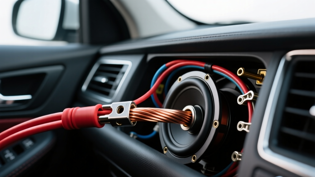
The Hidden Dangers of High-Power Subwoofer Wiring
When building a high-output car audio system, selecting the correct conductor size is only the first step. For amplifiers pushing 500W to 1500W RMS into low-impedance subwoofer loads, 12 gauge subwoofer wire is the gold standard. It provides the necessary cross-sectional area to handle massive AC current swings without introducing excessive resistance. However, purchasing premium 12 AWG wire does not guarantee a safe or high-fidelity installation.
As an automotive electrical specialist, I frequently diagnose systems suffering from thermal compression, alternator whine, and blown amplifier output stages. These failures rarely stem from the amplifier itself; they are the direct result of improper wire selection, poor termination, and hazardous routing. Below, we break down the five most critical mistakes installers make when working with 12 AWG speaker wire, alongside the engineering principles and safety protocols required to fix them.
Mistake 1: Falling for the CCA Deception (Copper Clad Aluminum)
The Problem
The mobile electronics market is flooded with inexpensive Copper Clad Aluminum (CCA) wire masquerading as premium Oxygen-Free Copper (OFC). CCA wire features a thin copper coating over an aluminum core. Because aluminum has roughly 61% of the conductivity of copper, a 12 AWG CCA wire actually performs electrically like a 14 AWG or even 15 AWG OFC wire. When you push 40 Amps of AC RMS current through a 1-ohm subwoofer load using CCA wire, the resistance generates excessive heat, leading to thermal compression and a dangerous voltage drop.
The Consequence
Your subwoofer will sound weak, the amplifier will run hotter as it struggles to maintain its damping factor, and the wire insulation can melt if routed through tight, unventilated channels.
The Expert Fix
Always verify that your wire complies with the CTA-2015 Standard for mobile audio wire. This standard mandates strict tolerances for strand count and cross-sectional area. Genuine 12 AWG OFC wire should contain roughly 65 to 73 strands of 0.25mm copper. If you scrape the cross-section of the wire and see silver/white metal underneath, it is CCA. Discard it immediately for high-power subwoofer runs.
Mistake 2: Bare Wire Under Amplifier Set-Screws
The Problem
Many installers strip the 12 gauge subwoofer wire, twist the bare strands, and shove them directly under the brass or steel set-screws of the amplifier's speaker terminals. This is a catastrophic error in automotive environments characterized by high humidity, temperature cycling, and constant vibration.
The Consequence
First, the set-screw will inevitably cut through the soft copper strands, reducing the effective wire gauge at the connection point. Second, bare copper exposed to the elements undergoes rapid galvanic corrosion, especially when in contact with dissimilar metals like brass terminals. This corrosion creates a high-resistance bottleneck. Finally, loose strands can stray and bridge the gap between the positive and negative terminals, resulting in a dead short that will instantly destroy the amplifier's output MOSFETs.
The Expert Fix
Never terminate bare wire into an amplifier. Use heavy-duty, adhesive-lined ring terminals or closed-end ferrules. Crimp the terminal using a dedicated hex-crimp tool (not a generic indent crimper) to ensure a cold-weld connection. Finally, apply 3M marine-grade adhesive heat shrink over the joint. The adhesive melts and seals the copper from oxygen and moisture, permanently halting corrosion.
Mistake 3: Inductive Coupling and Parallel Routing
The Problem
To save time, installers often zip-tie the 12 AWG subwoofer speaker wire directly alongside the 1/0 AWG main power cable running from the battery to the amplifier. Because subwoofer signals are low-frequency, some mistakenly believe they are immune to Electromagnetic Interference (EMI).
The Consequence
While you may not hear high-frequency hiss, running signal and power cables parallel to one another creates inductive coupling. The massive DC current fluctuations from the amplifier's power supply draw will induce a low-frequency voltage ripple into the speaker wire. This manifests as a muddy, distorted bass response and can trigger the amplifier's internal protection circuits due to back-EMF anomalies.
The Expert Fix
Route your 12 gauge subwoofer wire down the opposite side of the vehicle's center console or door sills compared to the main power wire. If the cables must intersect, they must cross at a strict 90-degree angle to minimize the magnetic field intersection area. Maintain a minimum separation of 18 inches whenever possible.
Mistake 4: Ignoring the Damping Factor Drop
The Problem
Damping factor is the amplifier's ability to control the physical movement of the subwoofer cone after the audio signal stops. It is calculated by dividing the load impedance by the total source resistance (amplifier output impedance + wire resistance). Installers often use 12 AWG wire for the positive run but downgrade to 16 AWG for the negative return path to save money or bend radius space.
The Consequence
The circuit is a continuous loop. The total resistance is the sum of both the positive and negative runs. By bottlenecking the return path, you artificially inflate the circuit resistance, severely degrading the damping factor. The result is "boomy," one-note bass that lacks transient punch and accuracy.
The Expert Fix
Always use matching 12 AWG OFC wire for both the positive and negative runs. According to SAE J1128 guidelines for automotive low-tension cable, maintaining uniform gauge throughout the entire circuit loop is critical for predictable current delivery and thermal management.
Mistake 5: Chassis Short Hazards in the Trunk Hatch
The Problem
When routing 12 gauge subwoofer wire through the rear deck, trunk hinges, or hatchback struts, installers often pass the wire through bare metal grommets or sharp sheet-metal seams without adequate protection.
The Consequence
Unlike the 12V main power wire (which has a fuse near the battery), speaker wire is driven by the amplifier's output stage. If the 12 AWG wire's insulation is chafed away by a vibrating trunk hinge and the bare copper touches the vehicle's grounded chassis, it creates a direct short to ground. The amplifier will attempt to drive current into the chassis, leading to instantaneous thermal failure of the output transistors and potentially melting the wire insulation inside the cabin.
The Expert Fix
Use split-loom tubing and high-quality rubber firewall grommets for all sheet-metal pass-throughs. Secure the wire with automotive-grade Tesa tape or felt-tape every 8 inches to prevent vibration-induced chafing. Never rely on zip-ties alone in areas with moving metal components.
12 AWG OFC vs. CCA: Technical Specification Chart
Understanding the physical and electrical differences between true OFC and deceptive CCA is vital for high-power subwoofer applications. The data below assumes a standard 20-foot round-trip run (10 ft positive, 10 ft negative) at 20°C.
| Specification | 12 AWG OFC (True) | 12 AWG CCA (Deceptive) |
|---|---|---|
| Cross-Sectional Area | 3.31 mm² | 3.31 mm² (but lower conductivity) |
| Strand Count (Typical) | 65 - 73 Strands | 40 - 50 Strands |
| Resistance per 1,000 ft | 1.59 Ohms | 2.60 Ohms (+63% Resistance) |
| Voltage Drop (20ft @ 40A RMS) | 0.127 Volts | 0.208 Volts |
| Max Ampacity (Chassis Wiring) | 60 Amps | 35 Amps |
| Thermal Rating | 105°C (Typical PVC/Teflon) | 85°C (Aluminum creeps at high heat) |
Pre-Flight Safety & Verification Checklist
Before powering on your amplifier and setting gains, run through this mandatory safety checklist to protect your equipment and your vehicle:
- Continuity Test: Use a digital multimeter (DMM) set to the Ohms setting. Verify continuity from the amplifier terminal to the subwoofer terminal on both positive and negative legs.
- Short Circuit Test: With the amplifier OFF and disconnected from the 12V power source, test between the positive speaker wire and the vehicle chassis. The DMM should read "OL" (Open Loop). Any resistance reading indicates a dangerous chassis short.
- Torque Verification:Ensure all amplifier set-screws are tightened to the manufacturer's specification (typically 1.5 to 2.0 Nm). Give the wire a firm tug to ensure the crimp and terminal are mechanically sound.
- Impedance Verification: Measure the final impedance at the amplifier terminals with your DMM. Ensure it matches the target load (e.g., 1.0, 2.0, or 4.0 ohms) before turning the system on.
By respecting the physics of electrical conductivity and adhering to strict automotive termination standards, your 12 gauge subwoofer wire will deliver clean, uncolored power to your subwoofers for the life of the vehicle.