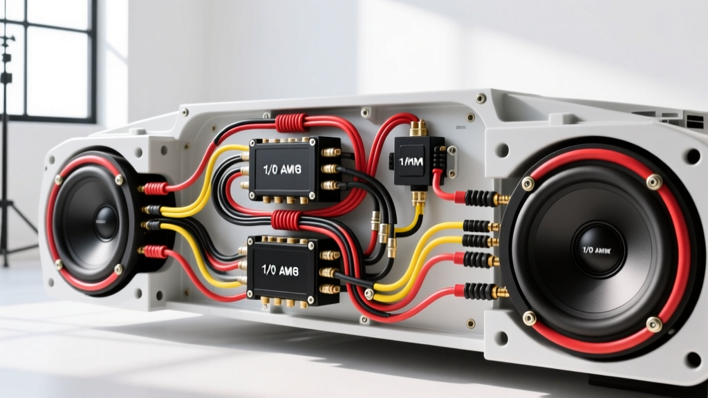
Introduction: The Reality of 1-Ohm Stability
When you search for a 1 ohm amp wiring diagram, you are stepping into the extreme upper limits of mobile audio electrical engineering. Pushing an amplifier to a 1-ohm load extracts maximum wattage, but it also generates immense heat and demands massive current delivery. A standard 12-volt automotive electrical system is not natively designed to sustain the 150 to 300+ ampere continuous draw required by a 1-ohm stable monoblock amplifier. This complete wiring diagram walkthrough will guide you through every node of the circuit, from the alternator stator to the subwoofer voice coils, ensuring your system performs flawlessly without triggering thermal protection or melting your vehicle's harness.
Phase 1: The Charging System and Big 3 Upgrade
Before running a single foot of power wire to the amplifier, you must address the source. A factory alternator typically outputs between 130A and 160A, which is entirely insufficient for a high-current 1-ohm system. Upgrading to a high-output alternator (250A to 350A) from manufacturers like Mechman or DC Power is mandatory. However, the alternator is only as good as the wiring that carries its output.
The Big 3 upgrade is the foundational step in any 1 ohm amp wiring diagram. According to SAE J1128 standards for low-tension primary cable, voltage drop across the chassis must be minimized. The Big 3 involves replacing or supplementing three critical factory ground and power paths with 1/0 AWG Oxygen-Free Copper (OFC) wire:
- Alternator Positive to Battery Positive: Bypasses the factory harness, delivering full alternator output directly to the battery bank.
- Engine Block to Chassis Ground: Ensures the engine block, which is isolated by rubber motor mounts, maintains a zero-resistance path to the chassis.
- Battery Negative to Chassis Ground: Completes the high-current return loop back to the alternator.
Phase 2: Main Power and Ground Routing Specifications
Tracing the power wire from the front of the vehicle to the trunk requires strict adherence to AWG ratings and overcurrent protection. For a 1-ohm monoblock pushing 2000W+ at 14.4V, your continuous current draw will exceed 200 amps.
Power Wire Selection and Fusing
You must use 1/0 AWG OFC wire. Never use Copper-Clad Aluminum (CCA) for a 1-ohm load; CCA has higher resistance and will overheat under sustained high-current draw, potentially causing a vehicle fire. The main power fuse must be installed within 18 inches of the battery positive terminal. For a 250A continuous draw, a 300A ANL fuse or a 350A Class T fuse is required. Class T fuses are highly recommended for lithium battery setups due to their superior interrupt rating.
The Critical Ground Connection
The ground wire is not merely a return path; it is the reference voltage for the amplifier's internal switching power supply. A poor ground will cause the amp to clip prematurely and enter protect mode. Follow these exact steps for the amplifier ground:
- Locate a structural, double-walled steel point in the trunk or hatch area, within 3 feet of the amplifier.
- Remove all paint, primer, and sound deadening down to bare, shiny metal using a rotary wire brush or 60-grit sandpaper.
- Crimp a heavy-duty, tinned copper ring terminal onto your 1/0 AWG ground wire using a hydraulic crimper. Seal the connection with dual-wall, adhesive-lined marine heat shrink.
- Bolt the terminal to the chassis using an M10 x 1.5mm zinc-plated steel bolt, a flat washer, and a star lock washer to bite into the bare metal. If the sheet metal is thin, use a steel backing plate on the opposite side to distribute the clamping force and prevent thread stripping.
Phase 3: Signal, RCA, and Remote Turn-On Integration
High-current power wiring generates significant electromagnetic interference (EMI). To prevent alternator whine and inductive noise, your RCA signal cables must be routed down the opposite side of the vehicle's interior from the 1/0 AWG power wire. Use high-quality, fully shielded twisted-pair RCA cables.
The remote turn-on wire (typically 18 AWG blue wire) signals the amplifier's internal relay to close. If you are using a high-current DSP or a factory head unit with a weak remote output (under 200mA), use a 12V automotive relay to trigger the amplifier. This prevents burning out the head unit's internal remote transistor. Connect the relay's coil ground to a clean chassis point, and the switched output directly to the amplifier's REM terminal.
Phase 4: Subwoofer Load Configuration (Wiring to 1 Ohm)
The speaker side of the 1 ohm amp wiring diagram requires precise mathematical configuration of the subwoofer voice coils. To achieve a safe, stable 1-ohm load using two Dual Voice Coil (DVC) 4-ohm subwoofers, you must wire the coils on each subwoofer in parallel, and then wire the two subwoofers in parallel at the amplifier terminals.
Step-by-Step DVC 4-Ohm Parallel Wiring
- Subwoofer A: Connect a jumper wire from Voice Coil 1 Positive (+) to Voice Coil 2 Positive (+). Connect a second jumper from Voice Coil 1 Negative (-) to Voice Coil 2 Negative (-). This drops Subwoofer A's impedance to 2 ohms.
- Subwoofer B: Repeat the exact same jumper process. Subwoofer B is now also a 2-ohm load.
- Amplifier Connection: Run a primary positive speaker wire from the Amp (+) terminal and split it to both Subwoofer A (+) and Subwoofer B (+). Run a primary negative speaker wire from the Amp (-) terminal and split it to both Subwoofer A (-) and Subwoofer B (-).
By wiring two 2-ohm loads in parallel, the final impedance presented to the amplifier is exactly 1 ohm. As detailed in comprehensive wiring guides like those from Crutchfield's subwoofer wiring resources, always verify the final impedance with a digital multimeter set to the 200-ohm resistance setting before applying power. The reading should be slightly above 1 ohm (typically 1.1 to 1.3 ohms) due to the DC resistance of the voice coils and speaker wire.
Technical Specification Chart: 1-Ohm Wiring Requirements
| Component | Specification / Material | Critical Notes |
|---|---|---|
| Main Power Wire | 1/0 AWG OFC (4933 Strands) | Never use CCA. Must be flexible and pure copper. |
| Main Fuse | 300A ANL or 350A Class T | Must be within 18 inches of battery positive. |
| Speaker Wire | 12 AWG or 10 AWG OFC | High current at 1 ohm requires thick speaker wire to prevent power loss. |
| Ground Hardware | M10 x 1.5mm Zinc-Plated Bolt | Use star washer and backing plate for sheet metal. |
| Terminals | Tinned Copper Ring Terminals | Hydraulic crimp and marine adhesive heat shrink required. |
Troubleshooting Voltage Drop and Thermal Shutdown
Even with a perfect 1 ohm amp wiring diagram, high-current systems can exhibit failure modes if the charging system cannot keep up. If your amplifier enters protect mode during heavy bass transients, do not immediately assume the amplifier is defective.
Diagnostic Decision Tree
- Measure Voltage at the Amp Terminals: With the system playing at moderate volume, use a digital multimeter to measure DC voltage directly at the amplifier's power and ground screw terminals. If voltage drops below 11.5V, you have a voltage drop issue.
- Check the Ground: Measure the voltage drop between the amplifier's ground terminal and the vehicle's bare chassis. It should read less than 0.05V. If it reads higher, disassemble, sand, and re-torque the ground connection.
- Verify Alternator Output: Measure voltage at the alternator's rear output stud while the system is playing hard. If the alternator is outputting 14.2V but the battery is at 12.8V, your Big 3 upgrade wiring is insufficient or you have a bad battery interconnect.
- Monitor Impedance Rise: As voice coils heat up, their resistance increases (thermal compression). A 1-ohm load can temporarily rise to 1.5 ohms, altering the amplifier's damping factor and power output. Ensure your subwoofer enclosure is properly vented to keep coil temperatures within safe operating limits.
Building a 1-ohm system is not for the faint of heart. It requires meticulous attention to wire gauge, termination quality, and charging system capacity. By following this walkthrough and adhering to strict automotive electrical standards, you will build a system that delivers earth-shattering bass with absolute reliability. For further reading on competition-level electrical setups, consult the International Auto Sound Challenge Association (IASCA) rulebooks for advanced wiring and safety compliance guidelines.