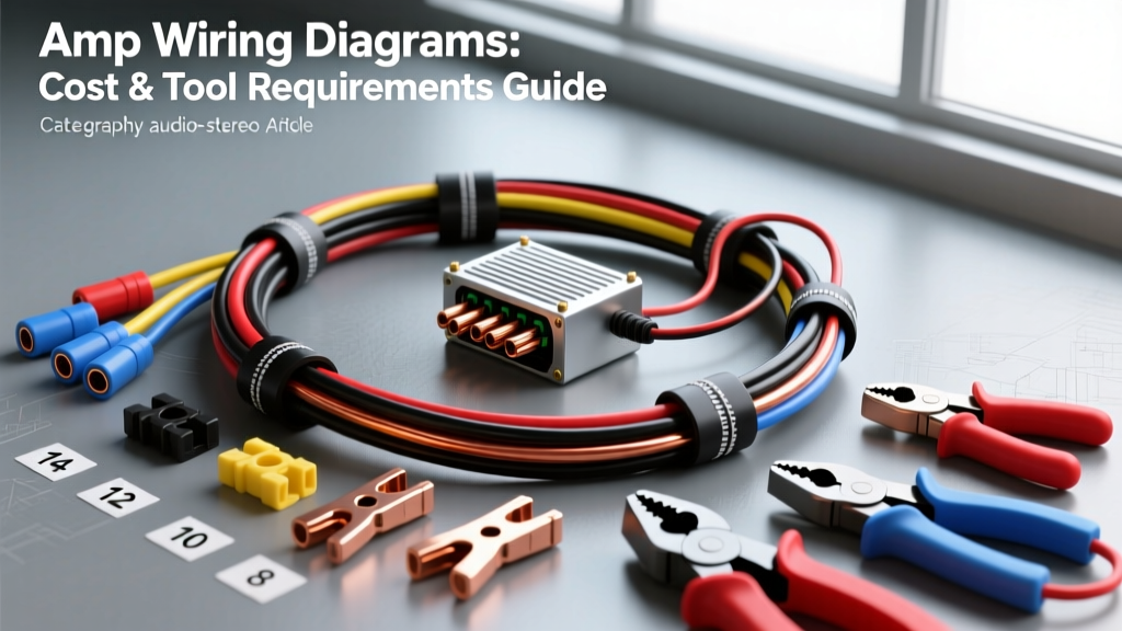
Decoding Amp Wiring Diagrams: From Schematic to Bill of Materials
When enthusiasts study amp wiring diagrams, they typically focus on signal flow and terminal destinations. However, professional automotive electricians view these schematics as strict financial and logistical blueprints. Every symbol on a car audio wiring diagram—from the primary ANL fuse block to the remote turn-on relay—dictates specific material costs, wire gauges, and specialized tooling requirements. Executing a high-current amplifier installation without cross-referencing your diagram against a comprehensive Bill of Materials (BOM) inevitably leads to mid-installation hardware shortages and compromised electrical safety.
Wire Gauge Material Costs: OFC vs. CCA Analysis
A standard amp wiring diagram for a 1,200W RMS Class D monoblock will specify 4 AWG power and ground conductors. The schematic rarely specifies the metallurgy, leaving the cost and performance variables to the installer. According to SAE J1128 standards for low-tension primary cable, current capacity relies heavily on conductor cross-section and thermal limits.
Oxygen-Free Copper (OFC)
- Cost: $3.50 - $5.00 per foot (4 AWG)
- Conductivity: 100% IACS (International Annealed Copper Standard)
- Max Current (Chassis): ~195 Amps
- Use Case: Mandatory for amplifiers exceeding 1,000W RMS or runs exceeding 15 feet to mitigate voltage drop below 12.8V at the amp's B+ terminal.
Copper Clad Aluminum (CCA)
- Cost: $1.20 - $1.80 per foot (4 AWG)
- Conductivity: ~68% IACS
- Max Current (Chassis): ~135 Amps (Requires upsizing to 2 AWG to match 4 AWG OFC)
- Use Case: Budget builds under 600W RMS. CCA is prone to galvanic corrosion when crimped with dissimilar metals, requiring dielectric grease and adhesive-lined heat shrink.
Mandatory Tooling: What the Diagram Demands
Interpreting the termination points on amp wiring diagrams reveals the tooling required. A diagram showing a ring terminal terminating at a distribution block or amplifier B+ post requires a specific crimp profile. Using side-cutters or pliers on 4 AWG or 1/0 AWG wire creates high-resistance cold joints, leading to thermal runaway and melted terminal blocks.
Crimping and Termination Tools
- Hex-Indent Crimper (8 AWG to 1/0 AWG): Essential for creating a gas-tight seal on ring terminals. A quality hex crimper costs between $45 and $85. This tool compresses the terminal into a hexagonal shape, maximizing surface contact area inside the amplifier's zinc-alloy terminal block.
- Wire Strippers: Standard automatic strippers fail on thick OFC insulation. A heavy-duty cable stripper or a specialized blade tool ($25-$40) is required to score the PVC jacket without nicking the copper strands, which reduces the wire's tensile strength and ampacity.
- Heat Gun with Reflector Nozzle: Adhesive-lined 3M heat shrink (required for all under-hood power connections to prevent moisture ingress) requires even, 360-degree heat application. A standard heat gun ($35) with a reflector nozzle ensures the inner meltable adhesive seals the wire strands completely.
Signal Integration and Hidden Schematic Costs
Modern amp wiring diagrams rarely show simple RCA connections due to the prevalence of factory-infotainment systems. If your diagram includes a 'High-Level Input' or 'Factory Integration' node, you must budget for signal conversion hardware and specialized harnesses. Referencing TE Connectivity automotive connector specifications is often necessary when identifying proprietary OEM plugs like the 22-pin Molex MX150 or 54-pin Quadlock connectors.
Line Output Converters (LOC) and DSPs
Tapping into factory speaker wires requires an active Line Output Converter (LOC) to flatten the factory EQ curve and restore a clean pre-amp signal. Budget $50 for a passive LOC or $150-$250 for an active, load-matching LOC (e.g., AudioControl LC2i or Kicker KEYLOC) that generates a 12V remote turn-on signal via DC offset detection, eliminating the need to tap the ignition or accessory fuse panel.
Distribution Blocks and Fusing Infrastructure
When an amp wiring diagram branches from a single 4 AWG main power line to multiple amplifiers, a distribution block becomes mandatory. Budgeting for a high-quality, solid-brass distribution block with insulating covers ($35-$50) is critical. Cheap aluminum blocks with thin nickel plating introduce contact resistance and thermal expansion mismatches. Furthermore, the diagram will dictate secondary fusing at the distribution block. If you are splitting a 4 AWG line to an 8 AWG branch for a 4-channel amplifier, you must install a 40A or 60A Mini-ANL or AGU fuse on that specific branch. This localized fusing protects the thinner 8 AWG wire from melting in the event of a short circuit before the main 120A battery fuse can react. Budget an additional $15-$25 for secondary fuse holders and elements.
Advanced Diagram Nodes: Capacitors and Lithium Upgrades
Some high-end amp wiring diagrams include a 1.5F to 3.0F capacitor wired in parallel with the amplifier's B+ and ground terminals. While traditional aluminum electrolytic capacitors ($40-$70) were once standard for preventing headlight dimming, modern electrical experts recommend 12V Lithium Iron Phosphate (LiFePO4) batteries. A small 8Ah LiFePO4 battery ($120-$150) wired as a secondary cell provides vastly superior current delivery and voltage stabilization. If your diagram includes a secondary battery node, you must also budget for a battery isolator or a high-current relay (like the Stinger SGP80, ~$35) to prevent the secondary battery from draining the primary starting battery when the engine is off.
Comprehensive Cost & Tool Matrix
The following matrix breaks down the estimated costs and tool requirements for a standard 1,000W Monoblock amplifier installation, based on a conventional 4 AWG OFC amp wiring diagram.
| Diagram Component | Specification | Required Tooling | Est. Cost (OFC) |
|---|---|---|---|
| Main Power Wire | 4 AWG OFC (15 ft) | Cable Stripper, Heat Gun | $65.00 |
| Primary Fuse | 120A ANL (within 18" of battery) | 1/2" Wrench, Hex Crimper | $22.00 |
| Ring Terminals | 4 AWG to 3/8" Stud, Adhesive Lined | Hex Crimper, Heat Gun | $12.00 |
| Ground Wire | 4 AWG OFC (3 ft) | Wire Brush, 10mm Socket | $15.00 |
| Remote Turn-On | 18 AWG Blue/White Primary Wire | Wire Strippers, Butt Connectors | $6.00 |
| Speaker Wire | 12 AWG OFC (20 ft) | Stripper, Crimper | $25.00 |
| Total Estimated BOM | $145.00 |
Expert Failure Modes: Budget vs. Performance Trade-offs
When attempting to cut costs on the materials dictated by amp wiring diagrams, installers frequently encounter specific electrical failure modes. Understanding these trade-offs is critical for long-term system reliability.
Alternator Whine and Ground Loops
A common cost-cutting measure is routing RCA signal cables parallel to the 4 AWG power wire to save time and zip-ties. Amp wiring diagrams explicitly show signal and power routing on opposite sides of the vehicle chassis to prevent electromagnetic interference (EMI). If budget constraints force a single-sided routing path, you must invest in high-quality, triple-shielded RCA interconnects ($40-$60) rather than standard unshielded cables to reject alternator diode switching noise.
Torque Specifications on Amplifier Terminals
Many budget amplifiers utilize soft zinc-alloy terminal blocks. Installers using standard nut drivers often overtighten the set screws, stripping the threads and creating a high-resistance connection that generates excessive heat under heavy bass transients. A calibrated inch-pound torque screwdriver set to 35-45 in-lbs (approx. 4-5 Nm) ensures a secure clamp without destroying the terminal block. While this tool adds $30 to your initial budget, it prevents catastrophic terminal failure.
The 'Big 3' Upgrade Requirement
If your amp wiring diagram indicates a total system draw exceeding 150 Amps (roughly 1,800W RMS), the factory alternator-to-battery and chassis-to-engine grounds become a bottleneck. Upgrading the 'Big 3' with 1/0 AWG OFC wire adds approximately $80 to your material costs but is mandatory to prevent headlight dimming and alternator diode burnout. Reference Crutchfield's amplifier installation guides for detailed chassis grounding procedures and paint-scraping techniques to ensure bare-metal contact for your ground terminals.
Ultimately, treating amp wiring diagrams as a strict procurement list ensures that your car audio system performs safely, efficiently, and without the hidden costs of mid-installation hardware runs or premature electrical failures.