Introduction to Active Loudspeaker Topologies and DSP Integration
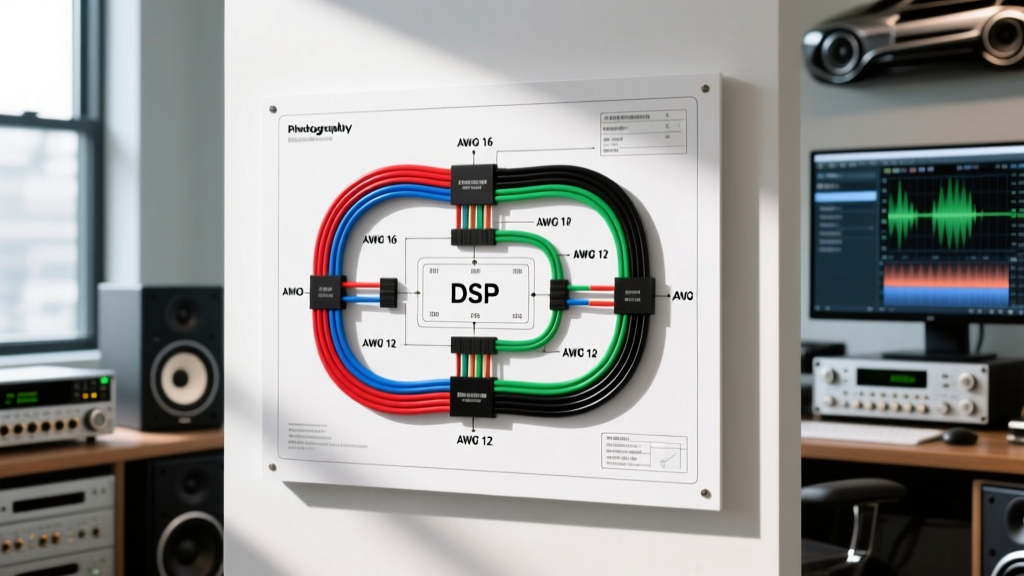
Transitioning from a passive to an active loudspeaker topology fundamentally alters the electrical and acoustic architecture of a mobile audio system. In a traditional passive setup, a single amplifier channel drives a full-range signal through a network of capacitors, inductors, and resistors to divide frequencies among the tweeter, midrange, and woofer. However, an advanced loudspeaker wiring diagram for an active 3-way system eliminates these lossy passive components entirely. Instead, the digital signal processor (DSP) handles all crossover functions in the digital domain, outputting discrete, pre-filtered analog signals via dedicated RCA or digital transport lines to individual amplifier channels. This requires a meticulous approach to wiring, impedance management, and phase alignment that goes far beyond basic positive and negative terminal connections.
When designing an active 3-way system, the installer must manage up to 12 dedicated amplifier channels (six for the left stage, six for the right stage, assuming a stereo configuration). This guide provides a deep technical dive into the wiring schematics, OEM harness bypass protocols, and Conductor sizing required to execute a reference-grade active loudspeaker installation without introducing inductive anomalies, thermal compression, or ground-loop noise.
Decoding the OEM Harness: Bypassing the Factory Amplifier
Before deploying aftermarket amplifiers and DSPs, the factory amplified signal must be intercepted and bypassed. Modern premium OEM audio systems (such as the BMW Harman Kardon or Ford B&O Unleashed) utilize complex multi-pin connectors to route low-level, actively crossed-over signals from the factory head unit to the OEM amplifier. To integrate an aftermarket DSP, we must tap into these low-level inputs before they reach the factory amp, or bypass the factory amp entirely using a bespoke wiring harness.
Consider the TE Connectivity MATEnet 22-pin connector, commonly found in late-model European amplified architectures. This connector carries both analog audio signals and CAN-bus data lines. An advanced loudspeaker wiring diagram must isolate the audio pins while terminating the CAN-bus pins with appropriate 120-ohm resistors to prevent the vehicle's ECU from throwing a fault code. Below is the critical pinout configuration for intercepting the front left and front right low-level analog signals.
| Pin Number | Signal Designation | OEM Wire Color | DSP Integration Note |
|---|---|---|---|
| 1 | Front Left (+) | White/Red | Route to DSP Analog In 1 (High-Z) |
| 2 | Front Left (-) | White/Brown | Do not ground; maintain differential pair |
| 3 | Front Right (+) | White/Blue | Route to DSP Analog In 2 (High-Z) |
| 4 | Front Right (-) | White/Yellow | Do not ground; maintain differential pair |
| 11 | CAN-High | Green/White | Terminate with 120Ω if OEM amp removed |
| 12 | CAN-Low | Green/Brown | Terminate with 120Ω if OEM amp removed |
Note: When bypassing the OEM amplifier, the factory load impedance is removed. Many modern Class-D OEM head units will shut down their audio output ICs if they detect an open circuit. To prevent this, your loudspeaker wiring diagram must include the installation of 10-ohm, 10-watt non-inductive dummy load resistors wired in parallel across the positive and negative terminals of the intercepted harness to simulate the presence of the OEM loudspeakers.
The Core Loudspeaker Wiring Diagram: DSP to Amplifier Stage
Once the DSP has processed the OEM signal—applying time alignment, parametric EQ, and active crossover slopes (typically 24dB/octave Linkwitz-Riley for midbass-to-midrange transitions)—the discrete signals must be routed to the aftermarket amplifiers. In a high-end active setup, unshielded RCA cables are unacceptable due to the high-density electromagnetic interference (EMI) generated by the vehicle's alternator and ignition coils.
Your wiring schematic should specify the use of shielded twisted-pair (STP) interconnects. The twist rate of the inner conductors (ideally 4 to 6 twists per inch) ensures that any induced EMI is applied equally to both the positive and negative signal legs. The amplifier's differential input stage then rejects this common-mode noise, resulting in a pristine noise floor. Furthermore, the shield braid must be grounded only at the amplifier end (the drain wire connected to the RCA outer shell at the amp, but left floating and insulated at the DSP end) to prevent ground loops that manifest as a 60Hz to 400Hz alternator whine.
Amplifier to Loudspeaker: AWG Selection and Impedance Matching
The physical wiring from the amplifier output terminals to the active loudspeaker voice coils is where many installations fail to meet electrical standards. The Consumer Technology Association (CTA) standard CTA-2015 provides strict guidelines for mobile electronics power ratings and conductor sizing. In an active system, because there is no passive crossover to introduce series resistance, the amplifier 'sees' the raw, dynamic impedance of the loudspeaker's voice coil. This demands ultra-low resistance wiring to maintain a high damping factor, ensuring the amplifier retains tight electromagnetic control over the speaker cone's excursion.
According to SAE J1128 and CTA guidelines, Oxygen-Free Copper (OFC) must be used. Copper-Clad Aluminum (CCA) suffers from higher resistivity and is prone to galvanic corrosion at the crimp terminals, which will severely degrade the damping factor of your midbass drivers. Below is the required AWG specification chart based on RMS wattage and maximum run length for active loudspeaker channels.
| Driver Type | Max RMS Power | Max Run Length (15 ft) | Required AWG (OFC) | Strand Count (Min) |
|---|---|---|---|---|
| Tweeter (1-inch dome) | 50W | 8 ft | 18 AWG | 41 strands (0.16mm) |
| Midrange (3-inch cone) | 100W | 12 ft | 16 AWG | 65 strands (0.16mm) |
| Midbass (6.5 to 8-inch) | 150W - 250W | 15 ft | 12 AWG | 168 strands (0.16mm) |
| Subwoofer (10 to 12-inch) | 600W+ | 10 ft | 8 AWG or 4 AWG | 735+ strands (0.16mm) |
High-Frequency Anomalies: Skin Effect and Inductance
When wiring the tweeter channels in an active 3-way system, the installer must account for the 'skin effect.' At high frequencies (10kHz and above), alternating current tends to travel predominantly along the outer surface of the conductor. While 18 AWG is sufficient for the current demands of a tweeter, using a highly stranded, fine-gauge wire (such as 30 AWG individual strands bundled into an 18 AWG jacket) increases the total surface area, marginally reducing high-frequency resistance and preserving the micro-dynamics of the upper harmonics. Additionally, keep tweeter wiring as far away from the main 1/0 AWG power distribution block as possible to prevent magnetic field coupling.
Troubleshooting Phase and Polarity Anomalies in Active Setups
In a passive system, the crossover network inherently shifts the phase of the drivers. In an active DSP system, phase alignment is managed via digital delay (measured in milliseconds or inches) and physical wiring polarity. However, a critical failure mode occurs when the absolute polarity of the loudspeaker wiring is inverted at the physical connection point, forcing the DSP to use excessive delay to 'wrap' the phase, which can smear transient response.
Always verify absolute polarity before finalizing the DSP tune. Pin 1 (Positive/Hot) on the amplifier must connect to the Red/Positive terminal on the loudspeaker, and Pin 2 (Negative/Cold) to the Black/Negative terminal. If a midrange driver exhibits a severe acoustic null at the crossover frequency (e.g., 3,500Hz) when summed with the tweeter, and digital phase inversion in the DSP software fails to resolve the peak, you are likely dealing with a physical wiring inversion or an OEM harness pinout error where the factory designated the 'negative' wire as the signal hot. Use a dedicated polarity tester or a Real-Time Analyzer (RTA) with a phase trace to confirm physical wiring integrity before applying DSP corrections.
Authoritative References and Further Reading
- Consumer Technology Association (CTA) - CTA-2015 Mobile Electronics Power Ratings and Conductor Standards.
- SAE International - J1128 Standard for Low Tension Primary Cable (Automotive Wire Specifications).
- JL Audio DSP Integration Guides - Best practices for differential signal routing and OEM harness bypassing.