Reading the Master Schematic: Car Audio Connector Types Explained
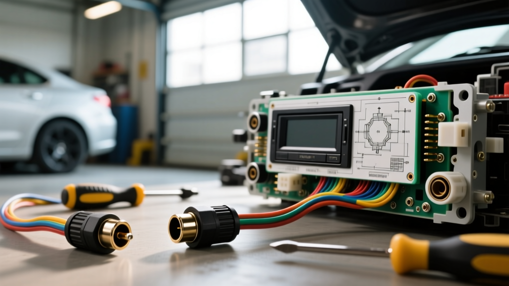
When analyzing a comprehensive car audio wiring diagram, the lines representing wire runs are only half the story. The true complexity of an installation lies in the physical nodes where these circuits mate: the connectors. Understanding specific car audio connector types is critical for maintaining signal integrity, preventing voltage drop, and ensuring long-term reliability in the harsh automotive environment. This complete wiring diagram walkthrough will trace the signal and power paths from the battery to the head unit, through the DSP, and out to the amplifiers, dissecting the exact connector specifications required at each junction.
The Head Unit Node: ISO 10487 vs. DIN Connectors
Tracing the diagram from the vehicle's fuse box to the aftermarket head unit, the first major interface is the main chassis harness. In modern vehicles, the ISO 10487 standard dictates the physical and electrical characteristics of these connections, though older or specific European models may still utilize the cylindrical DIN standard.
ISO 10487 Pinout and Wire Gauge Specifications
The ISO connector is divided into distinct blocks. Block A handles power and control signals, while Block B routes the low-level speaker outputs. When reading your wiring diagram, match the vehicle-side harness to the ISO adapter using the following standardized pinout:
| Block / Pin | Wire Color | Function | Recommended AWG | Diagram Notes |
|---|---|---|---|---|
| A - Pin 4 | Yellow | +12V Constant (Memory) | 16 - 14 AWG | Ties to battery via fuse; powers DSP memory. |
| A - Pin 7 | Red | +12V Switched (Accessory) | 16 - 14 AWG | Triggers head unit and remote turn-on relays. |
| A - Pin 8 | Black | Chassis Ground | 16 - 14 AWG | Must tie to clean bare metal; avoid daisy-chaining. |
| A - Pin 1 | Orange/Brown | Illumination | 18 AWG | Dims display; carries PWM signal in some modern CAN-bus systems. |
| A - Pin 5 | Blue/White | Power Antenna / Amp Remote | 18 AWG | Max 300mA output; use a relay for multiple amps. |
| B - Pin 1 & 2 | White / W-Black | Front Left (+ / -) | 18 - 16 AWG | Do not ground the negative (-) pins on active crossovers. |
The Legacy DIN Connector
If your diagram features a single 8-pin cylindrical plug, you are dealing with a DIN connector. Pin 4 is +12V Accessory, Pin 7 is +12V Constant, and Pin 8 is Ground. Because DIN pins are smaller and rely on friction rather than positive locking tabs, they are highly susceptible to "pin push-out" and vibration-induced arcing. Always apply dielectric grease to DIN pins and secure the barrel with a zip-tie to the chassis to prevent rotational stress.
Signal Transfer Node: RCA and High-Level Connectors
Moving down the schematic from the head unit pre-outs to the amplifier inputs, we encounter the analog signal transfer nodes. The quality of these car audio connector types directly dictates the system's signal-to-noise ratio (SNR).
RCA Pin Configurations and Shielding
RCA connectors are unbalanced, coaxial interfaces. The center pin carries the low-voltage audio signal (typically 2V to 5V RMS), while the outer barrel acts as the ground and electromagnetic shield. According to SAE J1113 standards regarding electromagnetic compatibility, unbalanced cables are highly susceptible to alternator whine and EMI. When routing RCA cables across the vehicle floorpan:
- Center Conductor: Must be oxygen-free copper (OFC) for optimal conductivity.
- Dielectric Layer: Foam or Teflon insulation prevents capacitance buildup, which can roll off high frequencies.
- Shielding: Look for twisted-pair internal wiring with a minimum 95% braided copper shield. The shield must only be grounded at the source (head unit) side to prevent ground loops, though in automotive 12V DC environments, the amplifier chassis ground often completes the circuit.
High-Level (Speaker Wire) Inputs
When integrating with OEM amplifiers, your diagram will show high-level signal taps. These utilize standard T-taps or Posi-Taps to splice into 16 AWG or 14 AWG factory speaker wires. The destination connector on the aftermarket DSP or amplifier is typically a Euroblock (pluggable screw terminal) or a proprietary Molex header. Always use a multimeter to verify phase and ensure the OEM signal does not exceed the 10V-13V maximum input threshold of your high-level inputs.
DSP and Amplifier Integration: Molex and Deutsch DT
Modern car audio wiring diagrams for complex, multi-channel active systems heavily feature high-density data and power connectors. Soldering directly to a DSP board is impossible; therefore, manufacturers rely on specialized automotive-grade connectors.
Molex MX150 and Mini-Fit Jr.
High-end DSPs (such as those from Helix, Audison, and JL Audio) utilize Molex connectors for their main harnesses. The MX150 series is sealed and features a 1.5mm pitch, making it ideal for routing through the vehicle's firewall or damp door sills where moisture is present.
| Connector Type | Pitch / Size | Current Rating | Wire Gauge Acceptance | Common Application |
|---|---|---|---|---|
| Molex MX150 (Sealed) | 1.50mm | Up to 16A per circuit | 14 - 20 AWG | DSP Main Harness, Door Pass-throughs |
| Molex Mini-Fit Jr. | 4.20mm | Up to 9A per circuit | 16 - 24 AWG | Internal Amp Power Headers, LED Control |
| Deutsch DT Series | Cylindrical / Wedgelock | 13A per contact | 14 - 20 AWG | Marine Audio, UTVs, External Amp Remotes |
Expert Tip: When crimping Molex pins, you must use a precision ratcheting crimper designed specifically for the MX150 terminal profile. A standard open-barrel crimper will deform the locking tang, causing the pin to back out of the housing when the harness is pulled through a tight rubber grommet.
OEM Integration: T-Harnesses and CAN-Bus Adapters
In late-model vehicles, the wiring diagram bypasses traditional ISO blocks entirely, relying instead on proprietary OEM data and power plugs (e.g., Ford 39-pin, Toyota 10+6 pin, RAM 52-pin). To avoid cutting factory wires, integration diagrams utilize "T-Harnesses."
A T-harness features a male plug that mates with the factory radio cavity and a female receptacle that accepts the OEM plug, with a third "tail" breaking out the necessary 12V constant, 12V accessory, ground, and speaker wires. For vehicles requiring data decryption (like GM Class 2 GMLAN or Chrysler CAN-Bus), the T-harness plugs into an interface module (e.g., iDatalink Maestro or PAC). These modules use standard 3.5mm data link cables or proprietary 4-pin serial connectors to communicate with the aftermarket head unit, translating digital CAN-bus messages into physical 12V trigger outputs and volume control signals.
High-Current Power Distribution Connectors
No wiring diagram walkthrough is complete without addressing the 12V power delivery nodes. For runs exceeding 4 AWG, traditional ring terminals become difficult to manage and prone to cracking under engine bay vibration.
- Anderson Powerpole (APP): Ideal for 4 AWG to 1/0 AWG connections. APP connectors use a flat wiping contact system that self-cleans upon insertion, minimizing contact resistance. They are frequently used in competition SPL builds to allow quick battery disconnects.
- ANL Fuse Holders: While technically a protective device, the bolt-down connections on ANL blocks serve as primary distribution nodes. Always use tinned copper lugs, heat shrink with adhesive lining, and torque the M6 or M8 bolts to the manufacturer's specification (typically 4-6 Nm) to prevent micro-arcing and thermal runaway.
Expert Troubleshooting: Connector Failure Modes
Even with a perfect schematic, physical connector degradation will ruin a system. Use this diagnostic tree when troubleshooting:
- Symptom: Intermittent head unit rebooting when hitting bumps.
Cause: ISO Block A Pin 8 (Ground) pin push-out or corrosion.
Fix: Extract the pin using a terminal removal tool, clean with electrical contact cleaner, and reseat until the locking barb clicks. - Symptom: High-pitched alternator whine that scales with RPM.
Cause: RCA shield ground compromised at the amplifier input, or RCA routed parallel to 4 AWG power wire.
Fix: Verify RCA outer barrel continuity to the amp chassis. Reroute signal cables at a 90-degree angle to power cables. - Symptom: DSP fails to retain tuning after vehicle sleep.
Cause: Voltage drop across the T-harness CAN-bus adapter waking the DSP via a "floating" ground.
Fix: Run a dedicated 16 AWG ground wire directly from the DSP chassis to a verified bare-metal chassis point, bypassing the T-harness ground.
Authoritative References
For further study on automotive electrical standards and connector specifications, consult the following resources:
- ISO 10487: Passenger cars - Connection of car radio to wiring harness - International Organization for Standardization.
- SAE J1113: Electromagnetic Compatibility Measurement Procedures and Limits - SAE International.
- Car Audio Wiring and Installation Guides - Crutchfield Technical Resources.
By treating every connector in your wiring diagram as a critical point of failure rather than a simple plug-and-play junction, you ensure that your car audio system delivers pristine sound and reliable operation for the life of the vehicle.