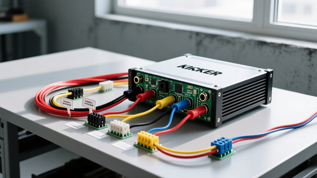
Introduction to Kicker Amplifier Diagnostics
When a high-output aftermarket audio system fails, the root cause is almost never the amplifier itself; it is almost always a deviation from the manufacturer's specified wiring topology. Kicker amplifiers—ranging from the compact CXA series to the competition-grade KX and DX lines—rely on strict voltage thresholds and impedance tolerances to operate correctly. Consulting the official Kicker Official Owner's Manuals and adhering to a precise Kicker amp wiring diagram is the only way to ensure longevity and optimal power transfer.
This step-by-step troubleshooting flow is designed for automotive electrical technicians and advanced DIY installers. We will bypass generic "check the fuse" advice and move directly into digital multimeter (DMM) diagnostics, voltage drop testing, and signal path verification to isolate faults in your Kicker amplifier installation.
Phase 1: Power (B+) and Ground (GND) Verification
The most common failure mode in high-current car audio systems is voltage starvation. Kicker amplifiers feature built-in Under-Voltage Lockout (UVLO) protection. If the voltage at the B+ terminal drops below 10.0V DC, or spikes above 16.0V DC, the amp will shut down and the protection LED will illuminate red.
Testing the Main Power Feed
- Set your DMM to DC Voltage (20V range).
- Place the black probe on a verified, unpainted chassis ground point (not the amp's ground terminal yet).
- Place the red probe directly on the amplifier's B+ set screw.
- With the engine off, you should read between 12.2V and 12.6V. With the engine running, you should read 13.8V to 14.4V.
- If voltage at the amp is more than 0.5V lower than the voltage at the battery positive terminal, your power wire is undersized or suffering from corrosion. According to the SAE J1128 Low Tension Primary Cable Standard, if you are using Copper-Clad Aluminum (CCA) wire instead of Oxygen-Free Copper (OFC), you must step up one AWG size to compensate for the higher electrical resistance of aluminum.
Voltage Drop Testing the Ground Circuit
A poor ground will cause alternator whine, clipping at low volumes, and thermal protection triggers. Do not rely on a visual inspection of the ground ring terminal.
- Keep the amplifier turned on and play a 50Hz sine wave test tone at 75% volume.
- Set your DMM to DC Millivolts (mV).
- Place the red probe directly on the amplifier's GND terminal.
- Place the black probe on a clean, bare metal point on the vehicle chassis within 12 inches of the ground bolt.
- A properly executed ground will show a voltage drop of less than 50mV (0.05V). If your reading exceeds 100mV, unbolt the terminal, sand the chassis to bare metal using 80-grit sandpaper, apply a dielectric grease coating over the terminal to prevent oxidation, and torque the M8 bolt to 15-20 Nm.
Phase 2: Remote Turn-On (REM) Circuit Diagnostics
The REM terminal requires a minimum of 5.0V DC to engage the internal power supply relays, but 12V is optimal. Kicker amplifiers draw very little current from the remote wire (typically less than 150mA), allowing you to daisy-chain multiple amplifiers using 18 AWG primary wire.
Diagnosing Remote Wire Voltage Drop
If your Kicker amp clicks on and off rapidly when the bass hits, the remote wire is likely suffering from voltage drop due to excessive length or a poor connection at the head unit's blue/white stripe wire.
- Test Point A: Measure voltage at the head unit's remote output. It should read a steady 12V when the unit is powered on.
- Test Point B: Measure voltage at the amplifier's REM terminal while the system is playing loudly. If it drops below 8V, you must install a 12V automotive relay. Use the head unit's remote wire to trigger the relay coil, and run a dedicated 14 AWG power feed from the B+ distribution block to the amplifier's REM terminal.
Note on FAST Harnesses: If you are integrating a Kicker amp using a factory integration harness (like the FAST plug-and-play system), verify that the Auto-Turn On feature is set correctly. If the factory radio lacks a dedicated 12V remote output, the Kicker amp must be set to "Audio" or "DC Offset" sensing mode via the integrated micro-switch on the end panel.
Phase 3: Signal Path and RCA Shielding Integrity
Ground loops and high-pitched alternator whine are signal path issues, not power issues. The Crutchfield Car Audio Wiring Guide emphasizes that RCA cables must never be routed parallel to power wires.
Isolating Ground Loop Noise
- Disconnect all RCA cables from the Kicker amplifier inputs.
- Turn the system on and listen to the speakers. If the alternator whine disappears, the noise is being injected via the RCA shields or the head unit's preamp stage.
- Using your DMM set to Ohms (Ω), measure the resistance between the outer metal shield of the RCA plug and the Kicker amplifier's metal chassis. It should read infinite (open loop). If it reads near 0Ω, the RCA cable's internal ground has shorted to the amp chassis, creating a ground loop. Replace the RCA cables immediately.
Phase 4: Speaker Load and Protection Mode Triggers
Kicker's KX and DX series mono amplifiers are stable down to 1 ohm, while stereo channels on the CXA series are typically stable to 2 ohms. Wiring subwoofers to an impedance lower than the amp's minimum threshold will trigger the short-circuit protection circuit.
Measuring True Impedance
Do not trust the nominal impedance printed on the subwoofer magnet. Voice coil resistance changes with temperature (thermal compression).
- Disconnect all speaker wires from the amplifier terminals.
- Set your DMM to the lowest Ohms setting (usually 200Ω).
- Short the DMM probes together to note the internal lead resistance (e.g., 0.2Ω).
- Measure across the speaker terminals at the end of the wire run. Subtract the lead resistance from your reading.
- A nominal 4-ohm subwoofer will typically read around 3.4Ω to 3.8Ω on a DMM. If you have two dual 4-ohm (DVC) subwoofers wired in parallel/series, ensure the final DMM reading is strictly above the amplifier's minimum stable ohm load listed in the Kicker amp wiring diagram.
Kicker CXA & KX Series Wiring Specifications Chart
Use this reference table to verify your wire gauge and fusing against Kicker's baseline engineering requirements. All wire sizes assume high-strand OFC. Fuses must be located within 18 inches of the vehicle battery positive terminal.
| Amplifier Model Class | Max Fuse Rating | Min. Power/Ground AWG | Min. Remote AWG | Min. Speaker Wire AWG |
|---|---|---|---|---|
| CXA Mono (e.g., CXA400.1) | 40A (ATO/ATC) | 8 AWG OFC | 18 AWG | 12 AWG |
| CXA Multi-Channel (e.g., CXA360.4) | 40A (ATO/ATC) | 8 AWG OFC | 18 AWG | 14 AWG |
| KX Mono (e.g., KX1600.1) | 150A (ANL) | 1/0 AWG OFC | 14 AWG | 8 AWG |
| KX Multi-Channel (e.g., KX800.5) | 100A (ANL) | 4 AWG OFC | 16 AWG | 12 AWG |
Protection LED Decision Tree
Kicker amplifiers utilize a dual-color LED indicator on the side or top panel. Use this decision tree to interpret the fault codes:
- Solid Green/Blue: Normal operation. Power, ground, remote, and impedance are within spec.
- Flashing Red: Thermal Protection. The internal heatsink has exceeded safe operating temperatures. Check for adequate airflow, verify impedance is not borderline, and reduce bass boost settings.
- Solid Red: Short Circuit or UVLO.
- Step 1: Disconnect all speaker wires. Turn amp on. If LED turns green, the fault is a shorted speaker wire or blown voice coil.
- Step 2: If LED stays red with speakers disconnected, measure B+ voltage. If below 10V, check alternator and battery health.
- Step 3: If B+ is 12V+ and LED is solid red with no speakers attached, the amplifier has suffered an internal output transistor failure and requires factory service.
By methodically following this Kicker amp wiring diagram troubleshooting flow, you eliminate guesswork, protect your hardware investment, and ensure your audio system delivers the distortion-free SPL it was engineered to produce.