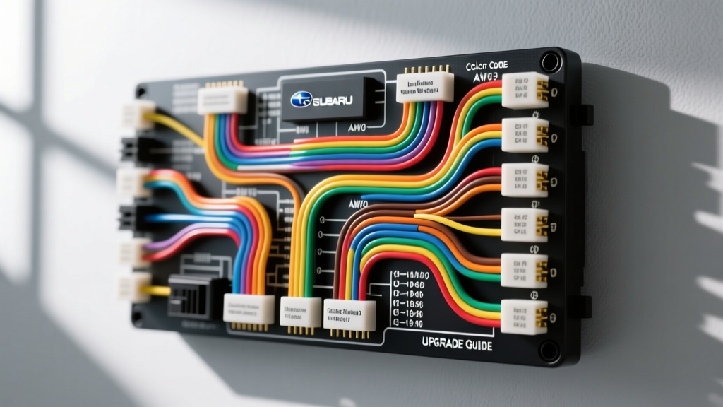
Planning Your Subaru Head Unit and Audio Upgrade
Upgrading the factory audio system in a Subaru—whether it is a WRX, Outback, Forester, or Impreza—requires a meticulous understanding of the vehicle's proprietary electrical architecture. Unlike older vehicles with simple analog 12V triggers, modern Subarus integrate the head unit into the CAN-bus network, managing everything from the chime module to the factory amplifier's wake-up sequence. Before you cut a single wire or remove the climate control trim bezels, you must map out your power delivery, speaker routing, and data interfaces. Understanding the exact color code stereo Subaru radio wiring diagram is the difference between a clean, plug-and-play installation and a hacked-up factory harness that causes parasitic battery draws or blown CAN-bus transceivers.
Decoding the Color Code Stereo Subaru Radio Wiring Diagram
Most 2008 to 2018 Subaru models utilize a dual-connector setup at the back of the factory radio: a 20-pin main harness (handling power, ground, and primary speakers) and a 10-pin auxiliary harness (handling CAN-bus data, illumination, and auxiliary inputs). When using an aftermarket wiring interface like the Metra 70-1761 or Scosche SU03B, you will be mating your aftermarket head unit's universal pigtail to these specific Subaru circuits.
Below is the definitive pinout and wire color reference for the standard 20-pin Subaru main harness. Always verify with a digital multimeter (DMM) before applying power, as mid-year production changes can occasionally alter secondary tracer colors.
| Pin | Function | Subaru Factory Wire Color | Aftermarket Equivalent | AWG / Notes |
|---|---|---|---|---|
| 13 | 12V Constant (Battery) | White/Red or Yellow | Yellow | 18 AWG (Fuse: 15A) |
| 14 | 12V Accessory (Switched) | Blue/Red or Red | Red | 18 AWG (Fuse: 10A) |
| 15 | Chassis Ground | Solid Black | Black | 18 AWG (Verify < 0.2 ohms) |
| 16 | Illumination (Dimmer) | Orange or Orange/White | Orange/White | 20 AWG (Do not tap LED circuits) |
| 17 | Power Antenna / Amp Remote | Purple/White | Blue/White | 20 AWG (Max 300mA draw) |
| 1 | Right Front Speaker (+) | Brown/White | Gray | 18 AWG |
| 2 | Right Front Speaker (-) | Brown/Black | Gray/Black | 18 AWG |
| 3 | Left Front Speaker (+) | Blue/Yellow | White | 18 AWG |
| 4 | Left Front Speaker (-) | Blue/Black | White/Black | 18 AWG |
| 5 | Right Rear Speaker (+) | Red/White | Purple | 18 AWG |
| 6 | Right Rear Speaker (-) | Red/Black | Purple/Black | 18 AWG |
| 7 | Left Rear Speaker (+) | Blue/White | Green | 18 AWG |
| 8 | Left Rear Speaker (-) | Blue/Black | Green/Black | 18 AWG |
Speaker Wire Routing and Phase Matching
Subaru's factory speaker wiring is notoriously thin, typically measuring 20 AWG to 22 AWG, which is sufficient for a 15-watt RMS head unit but entirely inadequate for aftermarket amplification. If your upgrade project involves bypassing the factory amplifier to run high-level signals or new speaker wire, you must upgrade to a minimum of 16 AWG Oxygen-Free Copper (OFC) wire, adhering to SAE J1128 standards for automotive primary cable.
When routing new wire through the Subaru door jambs, locate the rubber accordion boot between the A-pillar and the front doors. Use a stiff wire coat hanger and a dedicated wire-pulling lubricant to feed the 16 AWG wire through the factory grommet. Never pinch the wire against the door hinge mechanism, as the repeated articulation will shear the copper strands and cause a short against the chassis.
Dealing with the Subaru Starlink and Harman Kardon Amplifier
If your Subaru is equipped with the premium Harman Kardon (HK) or Starlink audio system, the factory head unit does not output standard speaker-level signals. Instead, it outputs low-level, differential balanced signals to the factory HK amplifier (usually located under the passenger seat or in the rear cargo area).
Modification Strategy A (The Bypass): The cleanest audio upgrade is to completely bypass the HK amplifier. This requires running new 16 AWG speaker wires from your aftermarket head unit's pigtail directly to each door speaker, bypassing the factory amp's output stage entirely. You will also need a PAC ROE-CH or similar data module to retain the steering wheel controls and factory chimes, as the CAN-bus network expects the HK amp to be present.
Modification Strategy B (The Integration): If you must retain the factory HK amp, you cannot use a standard Line Output Converter (LOC). You must use a differential-input LOC, such as the AudioControl LC2i or LC7i, which can safely sum and convert the balanced differential signals without introducing severe alternator whine or ground loop noise.
Power, Ground, and Remote Turn-On Specifications
For any project involving an external amplifier (subwoofer or 4-channel door amp), proper power delivery is non-negotiable. Subarus feature a unibody construction with extensive e-coat (anti-corrosion) paint, which acts as a severe electrical insulator.
- Power Wire: Run 4 AWG OFC wire from the positive battery terminal through the firewall. In left-hand drive Subarus, the main firewall grommet is located behind the clutch pedal (manual) or brake booster (automatic). Use a plastic trim removal tool to pierce the rubber nipple, never a sharp screwdriver which can slice the wire jacket later.
- Grounding: Do not use sheet metal screws. Locate a factory 10mm or 12mm seatbelt anchor bolt or chassis grounding stud. Remove the bolt, use 80-grit sandpaper to strip away the e-coat down to bare, shiny steel, and attach a tinned, closed-loop ring terminal. Coat the terminal in dielectric grease to prevent galvanic corrosion.
- Fusing: Install an ANL or Mini-ANL fuse holder within 12 inches of the positive battery terminal. For a 500W RMS system, an 80A fuse is appropriate for 4 AWG wire.
The CAN-Bus Sleep Mode Trap
A critical failure mode in Subaru audio upgrades is the remote turn-on wire. In older cars, the blue/white wire from the head unit safely triggered the amplifier. In modern CAN-bus Subarus, the factory radio does not output a dedicated 12V remote turn-on signal; it wakes the factory amp via a digital CAN-bus message. If you tap the cigarette lighter fuse or the accessory wire for your aftermarket amp's remote turn-on, the amplifier may fail to shut off when the car goes to sleep, resulting in a dead battery overnight. To solve this, use a CAN-bus interface module (like the Axxess XSVI-6202-NAV) that generates a proper 12V remote turn-on output synchronized with the vehicle's data network, or tap the rear wiper fuse in the interior fuse box, which is strictly switched and sleeps with the ignition.
Common Wiring Pitfalls and Troubleshooting
Even with a perfect color code stereo Subaru radio wiring diagram reference, DIY installers frequently encounter electrical gremlins. Use this diagnostic decision tree to isolate issues:
- Symptom: Head unit turns on, but display does not dim when headlights are activated.
Cause: The Orange/White illumination wire is unconnected or tapped into an LED circuit.
Fix: Connect the aftermarket Orange/White wire to the Subaru Orange illumination wire. Note: If the Subaru uses a PWM dimming circuit, you may need to install a 12V relay to provide a clean switched ground for the head unit's dimmer trigger. - Symptom: Severe alternator whine in the audio system that pitches up with engine RPM.
Cause: Ground loop caused by the factory HK amp ground or RCA cables routed parallel to power wires.
Fix: Ensure all aftermarket amplifiers share a single, unified ground point (ground loop isolator). Re-route RCA signal cables down the center console, and power wires down the driver's side rocker panel. - Symptom: Factory chimes (seatbelt, turn signal, door ajar) are completely missing after radio removal.
Cause: The factory radio acts as the speaker for the vehicle's Body Integrated Unit (BIU) warning chimes.
Fix: You must install a data retention module (such as the Metra Axxess ASWC-1 or equivalent Subaru CAN-bus interface) that includes a built-in piezo buzzer or routes the chime signal to an aftermarket speaker.
Expert Connection Standards
Never use twist-caps, electrical tape, or standard butt connectors for automotive audio wiring. The vibration profile of a Subaru, especially a WRX with a stiff suspension, will quickly shake loose mechanical crimps. For all head unit pigtail connections, use adhesive-lined marine-grade heat shrink butt connectors. Strip exactly 5/16ths of an inch of insulation, crimp with a dedicated ratcheting crimp tool, and apply heat until the adhesive sealant bleeds out of both ends. For amplifier power and ground connections, use a hydraulic crimper for 4 AWG and 8 AWG terminals to ensure a gas-tight, cold-weld connection. Following these standards, alongside a strict adherence to the factory pinouts, ensures your upgrade project delivers pristine audio and long-term electrical reliability.
For further vehicle-specific harness mappings and dash kit configurations, always cross-reference your exact VIN and trim level with the Crutchfield Vehicle Database before purchasing interface modules.