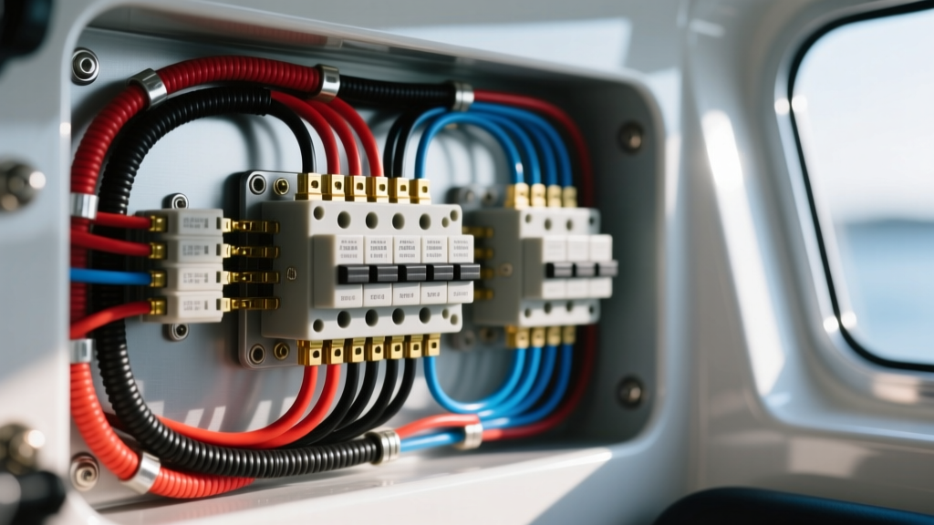
Introduction to Marine DC Power Distribution
Designing and troubleshooting a marine electrical system requires a fundamentally different approach than standard automotive wiring. While a car's electrical system operates in a relatively dry, stable environment, a vessel is subjected to saltwater corrosion, constant vibration, and severe stray current risks. A properly engineered boat fuse panel wiring diagram is not just a schematic; it is a critical safety blueprint governed heavily by the American Boat & Yacht Council (ABYC) E-11 standard for AC and DC electrical systems.
In this complete walkthrough, we will dissect a standard 12V DC marine distribution schematic. We will trace the current from the house battery bank through the main overcurrent protection, into the positive and negative busbars, and finally through the branch circuit fuse panel. Whether you are upgrading an older vessel with a modern Blue Sea Systems ST Blade panel or designing a custom dual-battery setup, understanding the anatomy of your boat fuse panel wiring diagram is essential for preventing electrical fires and ensuring reliable power delivery to your navigation and house loads.
Decoding the Boat Fuse Panel Wiring Diagram
A comprehensive marine DC schematic is divided into four distinct zones. Unlike automotive diagrams that often rely on the vehicle's steel chassis as a ground return, a boat's hull (especially fiberglass or wood) is non-conductive. Therefore, every single circuit must have a dedicated negative return wire routed back to a centralized negative busbar.
- Zone 1: The Source & Main Protection. This includes the house battery bank, the Marine Rated Battery Fuse (MRBF), and the main battery disconnect switch.
- Zone 2: The Distribution Busbars. Heavy-duty copper busbars that act as the central junction points for the main feed and multiple branch circuits.
- Zone 3: The Branch Circuit Panel. The primary fuse panel (typically ATC/ATO blade fuses) that protects individual loads like bilge pumps, navigation lights, and VHF radios.
- Zone 4: The Negative Return & Monitoring. The negative busbar, the battery monitor shunt, and the return path to the battery negative terminal.
ABYC-Compliant Wire Color Codes & AWG Sizing
Marine wire color codes differ significantly from automotive standards. Using the correct colors is vital for future troubleshooting and safety. Furthermore, marine wire must be tinned copper (Type 3 stranding) to resist black wire corrosion caused by salt air and moisture.
Table 1: ABYC E-11 DC Wire Color Standards
| Wire Color | Application | Notes |
|---|---|---|
| Red | DC Positive (Ungrounded) | Used for all positive branch and main feeds. |
| Yellow | DC Negative (Ground Return) | Never use black for DC ground on a boat to avoid AC/DC confusion. |
| Yellow w/ Red Stripe | Starting Motor Positive | Reserved exclusively for the engine starter circuit. |
| Orange | Distributor / Ignition | Used for engine ignition and alternator excitation. |
| Purple | Instrument Feed | Switched positive for gauges and instrumentation. |
| Blue | Navigation Lights | Dedicated positive feed for running/nav lights. |
Table 2: Main Feed AWG Sizing (3% Voltage Drop at 12V)
The main feed from the battery to the fuse panel must be sized based on the total continuous amperage draw and the total round-trip wire length. Below are baseline AWG requirements for a standard 15-foot round-trip run.
| Main Fuse Rating | Continuous Load (80%) | Minimum Wire Gauge (AWG) |
|---|---|---|
| 100A | 80A | 4 AWG |
| 150A | 120A | 2 AWG |
| 200A | 160A | 1/0 AWG |
| 250A | 200A | 2/0 AWG |
Step-by-Step Diagram Walkthrough: Routing & Terminations
Let's trace the current flow through a best-practice boat fuse panel wiring diagram, utilizing a Blue Sea Systems 12-Circuit ST Blade Fuse Block as our primary distribution hub.
Step 1: The Battery and MRBF Fuse
The schematic begins at the positive terminal of the house battery bank. According to ABYC E-11, any ungrounded conductor connected directly to a battery must have overcurrent protection within 7 inches of the terminal. We achieve this by installing an MRBF (Marine Rated Battery Fuse) directly onto the battery stud. For a standard house bank powering a 12-circuit panel and a windlass, a 250A MRBF is typical. The MRBF is ignition-protected, meaning it will not spark and ignite ambient hydrogen gas or bilge fumes if it blows.
Step 2: Main Disconnect and Positive Busbar
From the MRBF, a 2/0 AWG red tinned marine cable routes to a heavy-duty rotary battery disconnect switch. This switch allows you to isolate the house bank from the DC system when the vessel is unattended. The output of the switch routes to a Positive Distribution Busbar (rated for at least 300A continuous). The main feed from the fuse panel connects to one stud on this busbar, while other high-amperage direct loads (like a windlass relay or inverter positive) connect to adjacent studs.
Step 3: Branch Circuit Panel Integration
The positive feed from the busbar enters the main input stud of the ST Blade fuse panel. Inside the panel, a solid tin-plated copper busbar distributes the 12V positive to each individual blade fuse.
- Bilge Pump Circuit: Wired with a 3A ATC fuse. Crucially, the schematic shows this circuit bypassing the main battery disconnect switch, routing directly from the battery side of the disconnect to ensure the bilge pump operates even if the boat's DC system is switched off.
- VHF Radio Circuit: Wired with a 5A ATC fuse. The diagram dictates this wire should be routed directly to the battery or a dedicated low-noise busbar to prevent voltage drop and alternator whine during transmission.
- Navigation Lights: Wired with a 10A ATC fuse, utilizing the ABYC-mandated blue wire for the positive lead.
Step 4: The Negative Return Path and Shunt
Every yellow DC negative wire from the branch circuits routes back to a centralized Negative Busbar. This busbar must be the exact same ampacity rating as the positive busbar. From the negative busbar, a single massive 2/0 AWG yellow cable routes to a Battery Monitor Shunt (such as a Victron SmartShunt), and finally to the negative terminal of the house battery bank. The shunt acts as a precision resistor, allowing the battery monitor to measure every milliamp of current entering and leaving the bank. No other negative wires should be attached to the battery-side of the shunt, or the monitor's readings will be inaccurate.
Termination Standards: Crimping and Torque
A flawless boat fuse panel wiring diagram is useless if the physical terminations fail. Marine environments will rapidly destroy poorly crimped connections via capillary action and galvanic corrosion.
- Crimping: Never use solder on marine battery cables. Solder is brittle and will crack under engine vibration, leading to high resistance. Use a heavy-duty ratchet crimper with hexagonal dies designed for marine battery lugs.
- Heat Shrink: Every termination must be sealed with dual-wall, adhesive-lined heat shrink. When heated, the inner wall of meltable adhesive flows into the wire strands, creating a watertight seal that prevents salt air from wicking under the insulation.
- Torque Specifications: Loose connections generate heat. For standard 5/16-inch (M8) busbar and fuse panel studs, apply exactly 120 in-lbs (10 ft-lbs) of torque. Use a star washer or a specialized Belleville spring washer under the nut to maintain tension as the copper expands and contracts with temperature changes.
Diagnostic Troubleshooting for Marine Fuse Panels
When the physical wiring does not match the diagram, or when components degrade, specific failure modes emerge. Use this diagnostic matrix to troubleshoot common marine DC faults.
| Symptom | Probable Cause | Diagnostic Action |
|---|---|---|
| Blade fuse melts but does not blow | High resistance at the fuse blade contacts due to salt corrosion. | Perform a voltage drop test across the fuse while the circuit is loaded. A drop greater than 0.1V indicates corroded panel contacts. |
| Battery monitor shows phantom drain | Negative wire bypassing the shunt. | Inspect the battery negative terminal. Ensure the ONLY wire attached is the shunt's load-side cable. Move rogue grounds to the negative busbar. |
| VHF radio shuts off on transmit | Undersized wire or excessive voltage drop on the branch circuit. | Measure voltage at the VHF power plug during a 25W transmission. If it drops below 11.5V, upgrade the branch wire from 14 AWG to 10 AWG. |
| Green crust on busbar studs | Galvanic corrosion from dissimilar metals or lack of tinning. | Verify all lugs are tinned copper. Clean with a brass wire brush, apply anhydrous dielectric grease, and re-torque to 120 in-lbs. |
Authoritative References
To ensure your vessel remains safe and insurable, always cross-reference your custom schematics with established marine electrical authorities:
- American Boat & Yacht Council (ABYC) - The definitive source for the E-11 AC and DC Electrical Systems standard, which dictates wire sizing, overcurrent protection placement, and color codes.
- Blue Sea Systems - Manufacturer of marine-grade fuse panels and busbars. Their 'Circuit Wizard' tool and technical documents provide exact torque specs and AWG derating charts for marine environments.
- Marine How To - An extensive repository of practical marine electrical guides, including detailed tutorials on adhesive-lined heat shrink applications and battery monitor shunt wiring.
By strictly adhering to a validated boat fuse panel wiring diagram and utilizing marine-specific components, you ensure that your vessel's electrical system remains robust, safe, and capable of handling the harsh realities of the marine environment.