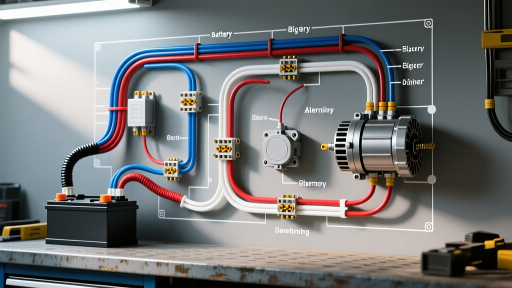
Understanding the Big 3 Wiring Diagram Architecture
When high-draw accessories like off-road light bars, massive audio amplifiers, or winches are added to a vehicle, the factory electrical system quickly reaches its limits. The OEM wiring harness is engineered for stock loads, typically utilizing 4 AWG or 6 AWG wire that degrades over time due to heat cycling and corrosion. Upgrading to a Big 3 wiring diagram replaces the three critical high-current paths with 1/0 AWG or 2/0 AWG Oxygen-Free Copper (OFC) cable. However, an improperly executed upgrade can introduce resistance, voltage drop, and severe Electronic Control Module (ECM) faults. This guide provides a definitive, step-by-step troubleshooting flow to diagnose and rectify failures in your Big 3 wiring diagram using live voltage drop testing.
Phase 1: Pre-Diagnostic Baseline & Tooling
Before dissecting the physical routing of your big 3 wiring diagram, you must establish a baseline under load. Resistance testing with an ohmmeter is entirely useless for high-current automotive circuits; a single strand of copper can show 0.01 ohms but will melt under a 120-amp load. You must perform voltage drop testing with the circuit energized.
Required Tooling
- True-RMS Digital Multimeter: Capable of reading DC millivolts (mV) accurately.
- Carbon Pile Load Tester: Alternatively, turn the HVAC blower to maximum, headlights to high beam, and engage the rear defroster to force the alternator to output 80+ amps.
- Thermal Imaging Camera: To instantly spot high-resistance crimps or corroded ring terminals under load.
Phase 2: Step-by-Step Voltage Drop Troubleshooting Flow
Set your multimeter to DC Volts. Start the engine and raise the RPM to 2,000. Apply the electrical load. Follow this sequential decision tree to isolate the fault in your Big 3 wiring diagram.
Node A: Alternator B+ to Battery Positive
Test: Place the red multimeter probe directly on the alternator B+ output stud (past the ring terminal). Place the black probe directly on the positive battery post (not the clamp).
Expected Result: Less than 0.20V (200mV) drop.
Troubleshooting Flow:
- If Drop > 0.20V: The issue is in the main charging wire. Check for CCA (Copper-Clad Aluminum) wire masquerading as OFC. CCA has 40% more resistance and will cause severe voltage drop. Verify the alternator B+ ring terminal is sized correctly (e.g., 5/16' for most Denso alternators, 3/8' for Delco Remy). A loose M8 alternator nut will arc and pit the copper.
- If Drop < 0.20V but Battery Voltage is < 13.8V: The wiring is fine. The alternator voltage regulator is likely failing, or the alternator sense wire is reading voltage at the wrong location.
Node B: Engine Block to Chassis Ground
Test: Place the red probe on a clean, bare metal spot on the engine block (e.g., an intake manifold bolt). Place the black probe on a clean, bare metal spot on the chassis/frame rail.
Expected Result: Less than 0.10V (100mV) drop.
Troubleshooting Flow:
- If Drop > 0.10V: The engine-to-chassis ground is compromised. This is the most common cause of 'alternator whine' in audio systems and erratic idle control. Inspect the grounding point. Did the installer use a star washer? Star washers bite into the ring terminal, not the chassis, and often snap under torque. Remove the bolt, sand the chassis to bare metal using 80-grit sandpaper, and reinstall using a serrated flange bolt or a flat washer with a serrated nut.
- If Drop < 0.10V but ECU throws U-Codes (CAN-Bus faults): Check the secondary OEM ground straps. The Big 3 upgrade does not negate the need for the factory ECU-specific ground nodes, which carry low-voltage, high-sensitivity signals.
Node C: Battery Negative to Chassis Ground
Test: Place the red probe on the negative battery post. Place the black probe on the chassis/frame rail where the negative cable terminates.
Expected Result: Less than 0.05V (50mV) drop.
Troubleshooting Flow:
- If Drop > 0.05V: The battery-to-chassis ground is failing. This causes the entire vehicle body to become a floating ground plane, leading to dimming headlights and PCM reset issues. Inspect the terminal crimp. If the adhesive-lined heat shrink is melted or the copper shows green/white oxidation, moisture has breached the crimp. Cut, strip, and re-crimp using a hydraulic tool.
- If Drop < 0.05V: The negative side of the Big 3 wiring diagram is functioning perfectly.
SAE Voltage Drop Threshold Reference Table
When evaluating your big 3 wiring diagram, use the following thresholds derived from SAE standards and heavy-duty automotive electrical practices. These values assume a minimum system load of 60 amps during testing.
| Circuit Path | Maximum Acceptable Drop | Optimal Target Drop | Common Failure Symptom if Exceeded |
|---|---|---|---|
| Alternator B+ to Battery (+) | 0.20V (200mV) | 0.05V - 0.10V | Battery undercharging, melted wire insulation |
| Engine Block to Chassis Frame | 0.10V (100mV) | 0.02V - 0.05V | Audio alternator whine, erratic idle, misfires |
| Battery (-) to Chassis Frame | 0.05V (50mV) | 0.01V - 0.03V | Headlight flicker, CAN-bus communication faults |
| Starter Solenoid to Battery (+) | 0.50V (500mV) | < 0.30V | Slow cranking, starter solenoid chatter |
Advanced Failure Modes: CAN-Bus Bounce and Terminal Crimping
A frequently overlooked aspect of the big 3 wiring diagram is the termination methodology. Many DIY installers use mechanical set-screw terminals or hammer-style crimpers. In high-vibration environments (like a diesel engine bay or off-road vehicle), mechanical set-screws will back out due to thermal expansion and contraction, leading to a high-resistance joint. Furthermore, applying dielectric grease between the mating surfaces of a ground joint is a catastrophic error; dielectric grease is an insulator and will artificially increase your voltage drop. Instead, use an anti-oxidant compound like Noalox, and apply it only to the exterior of the joint to seal out moisture.
For 1/0 AWG and 2/0 AWG OFC cable, you must use a hydraulic crimper with a hex or chevron die matched to the terminal manufacturer's specifications (e.g., 35-ton pressure for 2/0 AWG). Follow the crimp with 3:1 ratio adhesive-lined polyolefin heat shrink. When heated to 120°C, the inner thermoplastic adhesive melts and flows into the wire strands, creating a hermetic seal that prevents galvanic corrosion and capillary action from drawing moisture under the insulation.
If your vehicle experiences 'CAN-Bus bounce'—where the instrument cluster resets or the transmission shifts erratically under heavy electrical load—the ECU is referencing a floating ground. The factory ECU ground is often tied to the cylinder head or intake manifold. If your Engine-to-Chassis Big 3 ground is compromised, the heavy current from the alternator will seek the path of least resistance back to the battery, often routing through the ECU's low-current ground wires. This induces a voltage spike in the PCM, causing immediate logic resets. Tracing this requires verifying Node B in the troubleshooting flow above and ensuring the engine block ground is bolted to a dedicated, unpainted M10 boss on the block, torqued to 40-50 Nm.
Authoritative References
- MAD Enterprises: The 'Big 3' Wiring Upgrade Technical Guide - The foundational resource on high-current automotive charging circuit upgrades and OEM wiring limitations.
- AutoShop 101: Electrical Circuits and Voltage Drop Testing (PDF) - Comprehensive methodology on why live voltage drop testing supersedes resistance testing in automotive diagnostics.
- SAE J1128: Low Tension Primary Cable Standard - Society of Automotive Engineers specifications for battery cable insulation, strand count, and thermal ratings.