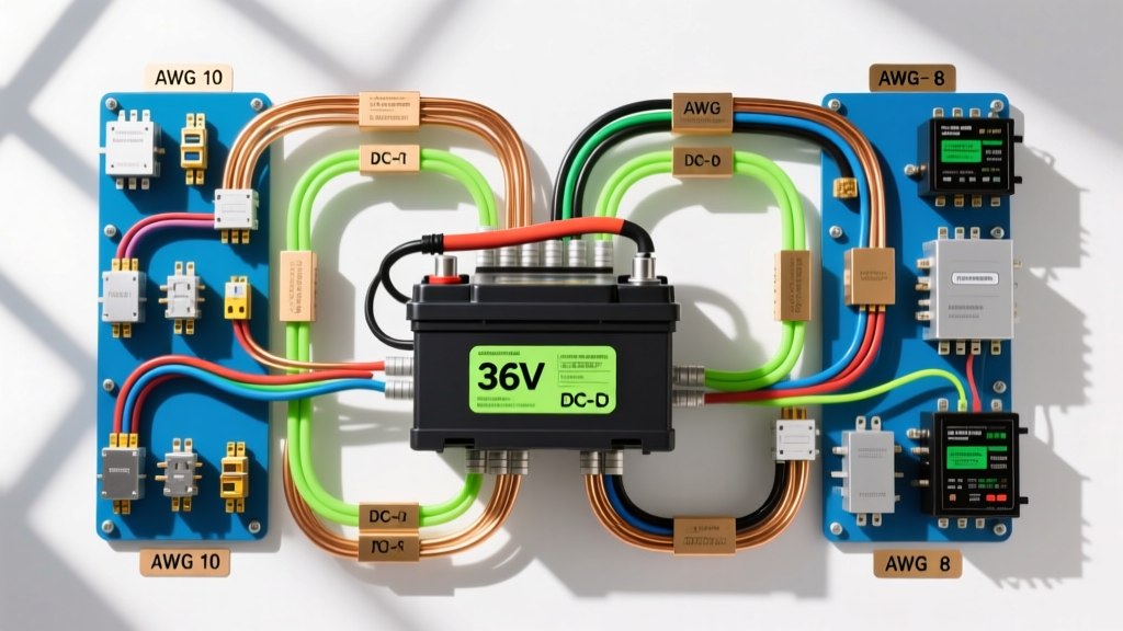
Decoding the 36V Architecture: Series vs. Native
When studying a standard 36v battery wiring diagram, the first critical decision is determining your cell architecture. A 36V nominal system is typically achieved in one of two ways: wiring three 12V drop-in LiFePO4 batteries in series, or building a native 12S (Lithium Iron Phosphate) or 10S (Lithium-Ion) raw cell pack. For automotive, marine trolling motors, and golf cart applications, the 3x 12V series configuration is the industry standard due to its modularity and integrated Battery Management System (BMS) protection. However, executing this diagram safely requires more than just connecting positive to negative; it demands precise high-current cable management, specialized crimping tooling, and rigorous adherence to overcurrent protection standards.
The complexity of a 36v battery wiring diagram increases significantly when integrating high-wattage inverters or heavy-draw DC motors. A 3000W inverter operating at 36V will pull approximately 85 amps continuously, with surge spikes exceeding 150 amps. At these current levels, improper tooling and substandard materials will result in severe voltage drop, thermal runaway, and catastrophic terminal failure. This guide breaks down the exact costs, specialized tools, and material specifications required to build a reliable, high-amperage 36V battery bank.
Mandatory Tooling for High-Current 36V Systems
You cannot safely execute a 36V high-current wiring diagram using standard automotive crimpers. Handling 1/0 AWG or 2/0 AWG fine-strand tinned copper requires mechanical advantage and precise die compression to ensure a gas-tight connection. Below is the mandatory tooling list for a professional-grade 36V build:
- Hydraulic Hex Crimper (12-Ton): Standard ratchet crimpers fail to provide adequate compression for 2/0 AWG lugs, leading to high-resistance joints. A 12-ton hydraulic crimper with hex-shaped dies (such as the IWISS or Titan series) ensures uniform compression without damaging the copper strands.
- Wire Strippers for 4/0 to 2/0 AWG: Using a utility knife to strip heavy-gauge battery cable inevitably nicks the outer strands, reducing the wire's cross-sectional area and creating a structural weak point. Dedicated heavy-duty cable strippers preserve the integrity of the fine-strand copper.
- Adhesive-Lined Heat Shrink & Propane Torch: Standard electrical tape is strictly prohibited in marine or mobile 36V environments. You must use 3:1 shrink ratio, dual-wall polyolefin tubing with an inner layer of thermoplastic adhesive. A localized propane torch or high-wattage industrial heat gun is required to melt the adhesive, creating a waterproof seal that prevents galvanic corrosion.
- Calibrated Torque Wrench (Inch-Pounds): Over-tightening battery terminals crushes the internal busbars of LiFePO4 batteries, while under-tightening causes arcing. A 1/4-inch drive torque wrench is non-negotiable.
- Digital Millivolt Meter & Infrared Thermometer: Essential for post-assembly validation to detect high-resistance connections under load.
Comprehensive Cost & Material Breakdown
Budgeting for a 36V system requires factoring in marine-grade or automotive-spec components. The table below outlines the estimated costs for a high-quality 3x 12V 100Ah LiFePO4 series build capable of sustaining 150A continuous discharge, adhering to guidelines set forth by the ABYC E-11 Standards for DC electrical systems.
| Component | Specification | Est. Cost (USD) |
|---|---|---|
| Primary Battery Cable | 2/0 AWG Fine-Strand Tinned Copper (15 ft) | $75.00 |
| Main Overcurrent Protection | Class T Fuse & Block (400A) | $55.00 |
| Series Interconnects | Custom 2/0 AWG Cables with 5/16" Ring Terminals | $40.00 |
| Busbars & Shunt | 250A Copper Busbars + 500A/50mV Shunt | $85.00 |
| Terminal Protection | $25.00 | |
| Specialized Tooling | 12-Ton Hydraulic Crimper & Wire Stripper Kit | $95.00 |
| Total Estimated Infrastructure Cost (Excluding Batteries) | $375.00 | |
Note: Never substitute standard brass or zinc-plated hardware for battery connections. Always use 316-grade stainless steel nuts and washers to prevent dissimilar metal corrosion, which rapidly increases contact resistance.
Executing the Wiring Sequence & Safety Protocols
The physical execution of a 36v battery wiring diagram must follow a strict sequence to prevent accidental short circuits and ensure accurate BMS telemetry. When wiring three 12V batteries in series (Battery A, Battery B, Battery C), follow this exact protocol:
- Preparation: Cut 2/0 AWG cable to length, allowing for service loops but avoiding excessive coiling, which can induce inductance. Strip exactly 1.25 inches of insulation. Brush the exposed copper with a wire brush and apply a thin layer of antioxidant compound.
- Crimping & Sealing: Slide the adhesive-lined heat shrink onto the cable before crimping. Insert the copper into the 5/16" tinned copper ring terminal. Use the hydraulic crimper with the 70mm² hex die. Apply heat until the adhesive purges slightly from the edges.
- Series Interconnects: Connect the Positive terminal of Battery A to the Negative terminal of Battery B. Connect the Positive of Battery B to the Negative of Battery C. Do not connect the main load cables yet.
- Main Negative Routing: Run the Main Negative from Battery A directly to the negative busbar or the battery monitor shunt. According to SAE J1128 and general DC best practices, the negative side should remain unfused to prevent a blown ground fuse from causing floating ground faults and erratic electronics behavior.
- Main Positive & Fusing: Run the Main Positive from Battery C to the positive busbar. Critical: The Class T fuse must be installed as close to the Battery C positive terminal as physically possible (within 7 inches). Class T fuses are mandatory for lithium banks due to their high Ampere Interrupting Capacity (AIC), which safely handles the massive fault currents lithium batteries can deliver compared to standard ANL fuses.
- Torque Application: Using your calibrated torque wrench, tighten all 5/16" terminal nuts to exactly 10-12 Nm (88-106 inch-pounds). Always hold the lug with a secondary wrench to prevent spinning the terminal stud, which will destroy the internal battery busbar.
Raw Cell 36V Packs: BMS Sense Wire Integration
If your 36v battery wiring diagram involves raw cells (e.g., a 12S LiFePO4 Prismatic cell build) rather than drop-in batteries, you must integrate an external BMS. The heavy gauge wiring remains similar, but the BMS sense wire harness requires extreme precision. Using 24 AWG silicone-jacketed wire, the balance leads must be soldered or crimped to the positive busbars of each cell group. The 13-pin JST-XH connector must be mapped sequentially: Pin 1 to the main battery negative, Pin 2 to Cell 1 Positive, continuing up to Pin 13 (Cell 12 Positive). Never plug the sense harness into the BMS until all heavy-current series links are verified and the harness has been tested with a multimeter to ensure adjacent pins show exactly 3.2V - 3.65V delta. A miswired harness will instantly destroy the BMS balancing circuitry.
Validation: Load Testing and Millivolt Drop Analysis
Completing the physical wiring is only half the process. To validate the integrity of your 36V system, perform a millivolt drop test under load. Connect your DC load (inverter or motor controller) and draw a sustained 50A. Using a digital multimeter set to DC millivolts, place the probes across each crimped joint and busbar connection. A properly executed hydraulic crimp with 2/0 AWG wire should show a voltage drop of less than 1.5 millivolts per connection. If any joint reads above 5 millivolts, or if an infrared thermometer detects a temperature delta greater than 10°F above ambient room temperature at the terminal, the connection must be cut, stripped, and re-crimped. For further circuit protection guidelines and fault-current analysis, refer to the engineering resources provided by Blue Sea Systems. By investing in the correct tooling and adhering to strict validation metrics, your 36V battery bank will deliver safe, reliable power for thousands of cycles.