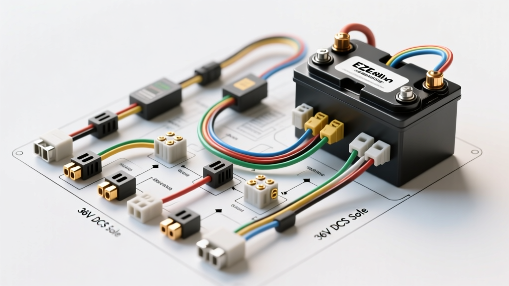
Understanding the 1995 EZGO Medalist 36V DCS Power Architecture
The 1995 EZGO Medalist represents a pivotal transition year in golf cart and Personal Transportation Vehicle (PTV) electrical systems. This model year primarily utilizes the 36V Drive Control System (DCS), moving away from the older resistor-based speed controls and early solid-state setups. When referencing the 1995 EZGO Medalist battery wiring diagram, technicians must understand that the power distribution network is divided into two distinct circuits: the high-current traction circuit (handling 200+ amps) and the low-current control circuit (handling under 5 amps). Misdiagnosing a voltage drop in the traction circuit as a faulty controller is a common and expensive mistake. Proper troubleshooting requires a systematic, step-by-step flow that isolates the battery bank, the main solenoid, the Forward and Reverse (F&R) switch, and the DCS controller.
Before initiating any diagnostic flow, verify the baseline architecture. The 1995 Medalist 36V system relies on six 6V deep-cycle lead-acid batteries (typically Group GC2, such as the Trojan T-105) wired in series. The main power cables must adhere to SAE J1128 specifications for low-tension primary cable, utilizing high-strand-count copper to mitigate voltage drop under heavy inductive loads. For a comprehensive visual reference of the factory harness routing, the Cartsaholic EZGO Wiring Archives provides excellent OEM diagram reproductions.
Core Battery Wiring Specifications & Diagram Reference
Accurate troubleshooting requires knowing the exact specifications of the wiring harness. Refer to the table below for the critical high-current nodes found on the 1995 Medalist battery wiring diagram.
| Circuit Node | Wire Color / Type | AWG Size | Terminal Type | Torque Specification |
|---|---|---|---|---|
| Battery Interconnects | Bare Copper / Red-Black Heat Shrink | 4 AWG | 5/16' Ring (Lugged) | 110 - 130 in-lbs |
| Main B+ to Solenoid | Red Heavy-Duty Insulated | 2 AWG | 5/16' Ring | 120 - 140 in-lbs |
| Solenoid to Controller B+ | Red Heavy-Duty Insulated | 2 AWG | 5/16' Ring | 120 - 140 in-lbs |
| Controller M- to F&R Switch | Yellow Heavy-Duty | 4 AWG | 5/16' Ring | 110 - 130 in-lbs |
| F&R Switch to Motor | Yellow / Blue Heavy-Duty | 4 AWG | 5/16' Ring or 3/8' | 120 - 150 in-lbs |
| Solenoid Coil Activation | Yellow / Black-White (Control) | 14 AWG | 10-32 Stud / Spade | 35 - 45 in-lbs |
Troubleshooting Flow 1: Solenoid Fails to Engage (No Click)
When you press the accelerator pedal and the solenoid remains silent, the issue lies within the low-current control circuit or the battery bank's baseline voltage. The DCS controller requires a minimum threshold voltage to close the internal logic gate and send power to the solenoid coil.
- Step 1: Verify Bank Voltage. Set your digital multimeter (DMM) to DC Volts. Place the black probe on the main negative battery post and the red probe on the main positive battery post. A fully charged 36V system must read between 38.2V and 38.4V. If the reading is below 36.0V, the DCS controller will trigger the low-voltage lockout, preventing solenoid engagement to protect the batteries from deep discharge.
- Step 2: Check Key and Tow/Run Switches. Verify 36V at the input side of the key switch. Turn the key to 'ON' and verify 36V on the output side. Next, locate the Tow/Run switch under the passenger seat. Ensure it is in the 'Run' position. If the switch is in 'Tow', the controller logic is physically severed from the solenoid activation circuit.
- Step 3: Test the F&R Microswitches. The 1995 Medalist F&R switch contains mechanical high-current contacts and low-current microswitches. The microswitch on the active side (Forward or Reverse) must close to complete the activation circuit. Unplug the 4-pin microswitch harness. Use the DMM in continuity mode to test the microswitch pins. If the switch fails to close when the lever is thrown, the solenoid will not receive the activation signal.
- Step 4: Solenoid Coil Verification. If all upstream switches pass, test the solenoid coil. Disconnect the two small activation wires. Apply 36V directly from the battery bank to the small terminals (polarity does not matter on standard EZGO solenoids). If you hear a definitive, loud 'clack', the coil is functional, and the fault lies in the DCS controller's internal MOSFET driver or a broken 14 AWG control wire.
Troubleshooting Flow 2: Solenoid Clicks, But Cart Will Not Move
A clicking solenoid indicates that the control circuit is functioning, but the high-current traction circuit is failing to deliver power to the motor. This is where the 1995 EZGO Medalist battery wiring diagram becomes critical for tracing voltage drops across heavy-gauge cables.
- Step 1: The Solenoid Voltage Drop Test. With the cart jacked up and rear wheels off the ground, press the accelerator to engage the solenoid. Place your DMM probes directly on the two large 5/16' solenoid studs. A healthy solenoid will show a voltage drop of less than 0.2V under load. If you read full battery voltage (e.g., 36V) across the large studs while engaged, the internal copper contact disc is severely pitted or welded open. Replace the solenoid.
- Step 2: F&R Switch Main Contact Inspection. If the solenoid passes, move to the F&R switch. The mechanical lever slides a copper contactor across four large studs. Over time, arcing causes carbon buildup. Disconnect the battery bank. Remove the F&R switch and inspect the internal copper pads. If they are pitted or blackened, clean them with a fine-grit abrasive pad or replace the switch assembly. Reassemble and test for continuity between the input and output studs in both Forward and Reverse positions.
- Step 3: Motor Brush and Armature Check. If power successfully navigates the F&R switch, the issue may be at the motor. Remove the four 5/16' nuts securing the motor end cap. Inspect the four carbon brushes. If they are shorter than 3/4 inch, or if the spring tension is weak, the motor will not commutate. Additionally, check the armature commutator bars for severe grooving or mica protrusion, which can prevent the brushes from making solid electrical contact.
Troubleshooting Flow 3: Intermittent Power Loss and Thermal Runaway
Intermittent power loss, often accompanied by a burning smell or melting insulation, is a hallmark of high-resistance connections in the battery wiring harness. According to National Association of Battery and Solar Associates (NABSA) technical guidelines, a loose connection carrying 200 amps will generate massive localized heat, leading to thermal runaway and melted cable lugs.
- Inspect Battery Interconnects: The 4 AWG interconnect cables between the six 6V batteries are subject to constant vibration and corrosive sulfuric acid off-gassing. Remove all interconnects, neutralize any acid buildup with a baking soda solution, and wire-brush the lead battery posts until they shine. Reinstall and torque strictly to 110-130 in-lbs. Overtorquing will strip the soft lead posts; undertorquing will cause arcing.
- Verify DCS Controller B+ and B- Terminals: Follow the 2 AWG red wire from the solenoid to the DCS controller B+ terminal. Ensure the ring terminal is flush against the controller bus bar. A loose B+ connection will cause the controller to read erratic voltage spikes, triggering its internal over-voltage protection and shutting down the cart mid-drive.
- Charge Receptacle Bypass Test: The 3-pin Powerwise charge receptacle is wired directly to the main battery bank. If the internal diode or wiring inside the receptacle shorts out, it can drag down the main system voltage. Unplug the receptacle harness from the main B+ and B- battery terminals. If the intermittent power loss ceases, the charge receptacle assembly is internally faulted and must be replaced.
Safety Protocols and Final Diagnostic Verification
Working on a 36V high-current DC system presents severe arc-flash and short-circuit hazards. Before removing any 2 AWG or 4 AWG cables, you must physically disconnect the main negative battery cable from the battery bank and isolate it with a non-conductive cap. Never use standard automotive fuse testers on the high-current traction circuit; use a DMM rated for CAT III or higher. When reassembling the battery wiring harness based on the 1995 EZGO Medalist battery wiring diagram, always apply a thin layer of dielectric grease or petroleum jelly over the torqued battery terminals to prevent future oxidation. By following this structured, step-by-step troubleshooting flow, you can accurately isolate faults in the DCS power distribution network without resorting to unnecessary and costly component replacements.