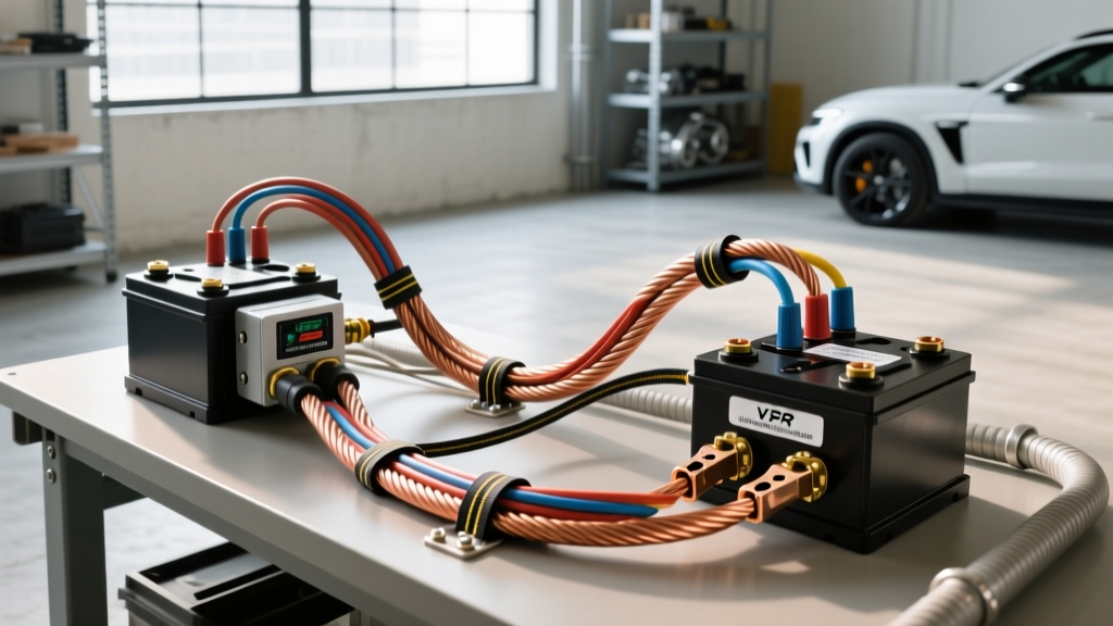
Introduction to High-Current 4 AWG Routing
When upgrading an off-road vehicle, overland rig, or heavy-duty truck to support high-draw accessories like winches, massive lighting arrays, and onboard air compressors, the factory wiring harness is entirely inadequate. Upgrading the main charging and distribution circuits requires heavy-duty cabling. This complete wiring diagram walkthrough focuses on the strategic deployment of 4 gauge power wire (4 AWG) in a dual-battery system managed by a Voltage Sensitive Relay (VSR). According to MAD Electrical automotive wiring standards, 4 AWG copper cable is the optimal threshold for handling 150 to 190 amps of continuous current while maintaining an acceptable voltage drop over standard engine-bay distances.
In this guide, we will trace the schematic from a high-output alternator through the primary battery, across the VSR isolator, and into the auxiliary battery and main distribution block. We will cover specific terminal sizes, crimping methodologies, fuse placements, and the critical grounding nodes required to complete the circuit safely.
System Overview: The High-Output Dual Battery Schematic
Before cutting any cable, it is vital to understand the topology of this specific 4 gauge power wire diagram. This setup assumes a 220-amp aftermarket alternator, a primary starting battery, a National Luna or Redarc-style VSR, and a deep-cycle auxiliary battery. The primary goal of using 4 AWG wire throughout the main positive and negative trunks is to minimize voltage drop, ensuring the auxiliary battery receives a full 14.2V charging voltage from the alternator, even when high-draw loads are active.
The system relies on SAE J1128 compliant SXL (Cross-Linked) insulated copper wire. SXL insulation is rated for 125°C, making it highly resistant to the radiant heat generated by exhaust manifolds and the alternator casing. Below is the step-by-step schematic walkthrough.
Node 1: Alternator Output to Primary Battery
The factory alternator output wire is typically 8 or 10 AWG, which will bottleneck a 220A alternator and cause severe voltage drop and wire heating. Diagram Step 1 involves running a continuous length of red 4 gauge power wire from the alternator's main output stud (typically a 5/16' or 8mm ring terminal) directly to the primary battery's positive post.
- Wire Color: Red (Main Charging Power)
- Protection: A 250A Class T or ANL fuse must be installed within 7 inches of the primary battery positive terminal to protect the entire 4 AWG run from a dead short.
- Routing: Route the wire along the inner fender, avoiding the exhaust. Use split-loom tubing and secure with adhesive-backed P-clamps every 12 inches.
Node 2: Primary Battery to VSR (Voltage Sensitive Relay)
From the primary battery's positive post (sharing the same heavy-duty busbar or military-style terminal clamp), a second 4 AWG red cable routes to the 'Start Battery' stud on the VSR. This cable must also be protected. While the VSR handles the switching, a 200A ANL fuse should be placed inline on this 4 gauge power wire segment to protect the isolator's internal coil and contacts from catastrophic surge events during winching operations that might back-feed through the chassis.
Node 3: VSR to Auxiliary Battery
The 'House/Aux Battery' stud on the VSR connects to the auxiliary battery located in the rear cargo area or passenger side fender well. Because this run is often 10 to 15 feet long, 4 gauge power wire is the absolute minimum requirement to prevent voltage drop. A 15-foot run of 2 AWG is ideal, but 4 AWG is acceptable if the continuous draw on the aux battery does not exceed 120A. For this diagram, we are utilizing 4 AWG red wire paired with a 150A ANL fuse located exactly 7 inches from the auxiliary battery positive terminal.
Node 4: Auxiliary Battery to Main Distribution Block
From the auxiliary battery positive, a short 18-inch jumper of 4 AWG red wire connects to a high-amperage marine-grade busbar or distribution block (such as a Blue Sea Systems 250A busbar). From this block, smaller gauge wires (8 AWG, 10 AWG, 12 AWG) branch out to individual relays, fuse panels, and accessories like fridges, inverters, and lighting.
The Grounding Network: Completing the 4 AWG Circuit
A common failure point in dual-battery diagrams is undersizing the ground wires. Electricity must return to the source. If your positive trunks are 4 gauge power wire, your primary ground trunks must match this capacity. The factory engine-to-chassis ground strap is often a braided 6 AWG wire that will choke a 220A alternator.
Grounding Walkthrough:
- Alternator Case to Engine Block: Ensure the alternator is grounded through its mounting bracket. If using a powder-coated bracket, add a 4 AWG black ground wire from the alternator casing ground lug to a clean, bare-metal point on the engine block.
- Engine Block to Chassis: Upgrade the factory ground strap to a 4 AWG black braided or SXL copper cable. Connect it from a clean bolt on the cylinder head to a dedicated, paint-scraped grounding stud on the firewall or inner fender.
- Chassis to Auxiliary Battery: Run a 4 AWG black wire from the auxiliary battery negative terminal to a heavy-duty chassis ground point. Use a star washer to bite through the paint and ensure bare metal-to-copper contact, followed by a coating of di-electric grease to prevent galvanic corrosion.
4 AWG Cable Specifications & Voltage Drop Chart
Understanding the physics of your 4 gauge power wire is crucial for safe system design. The following table illustrates the ampacity and voltage drop characteristics of pure copper 4 AWG wire (based on SAE J1128 standards) over a standard 10-foot one-way run (20-foot total circuit length).
| Current Draw (Amps) | Voltage Drop (10ft Run) | Percentage Drop (14.2V System) | Wire Temp Rating (SXL) | Safety Status |
|---|---|---|---|---|
| 50A | 0.12V | 0.84% | 125°C | Optimal |
| 100A | 0.24V | 1.69% | 125°C | Safe / Standard |
| 150A | 0.36V | 2.53% | 125°C | Maximum Continuous |
| 190A | 0.46V | 3.23% | 125°C | Absolute Limit |
Note: As outlined by Blue Sea Systems circuit protection guidelines, voltage drop should ideally remain below 3% for critical charging circuits. If your auxiliary battery is located 15+ feet from the alternator, you must step up to 2 AWG or 1/0 AWG wire to maintain this threshold.
Terminal Preparation and Crimping Methodology
The most vulnerable point in any 4 gauge power wire diagram is the termination. Poorly crimped 4 AWG terminals introduce high resistance, leading to localized heat buildup, melted insulation, and eventual voltage starvation. Soldering 4 AWG battery lugs is generally discouraged in high-vibration automotive environments because solder can wick up into the wire strands under the insulation, creating a rigid, brittle section that will snap under engine harmonics.
Proper Crimping Steps for 4 AWG Lugs:
- Stripping: Use a heavy-duty wire stripper to remove exactly 5/8' of insulation. Do not nick the outer copper strands, as this reduces the cross-sectional area and creates a weak point.
- Oxidation Inhibitor: Apply a small amount of No-Ox or dielectric grease inside the barrel of the copper lug before inserting the wire. This prevents moisture ingress and galvanic corrosion.
- The Crimp: Insert the wire fully into the lug barrel. Use a dedicated hex-crimp tool or a hydraulic crimper designed for 4 AWG. A hex crimp compresses the copper barrel evenly around the strands, cold-welding them together without cutting individual strands like a standard indenter crimper might.
- Sealing: Slide a piece of dual-wall, adhesive-lined heat shrink tubing over the connection. Apply heat evenly until the adhesive purges slightly from the edges, creating a watertight seal against battery acid and road salt.
Troubleshooting Voltage Drop and Connection Failures
Even with a perfect diagram, real-world variables can cause system failures. If your auxiliary battery is failing to charge, or your winch is bogging down prematurely, use a digital multimeter to perform a live voltage drop test across your 4 gauge power wire segments.
- Symptom: Alternator outputs 14.4V, but Primary Battery reads 13.8V under load.
- Diagnosis: High resistance in the Alternator-to-Battery 4 AWG wire or the main ground strap.
- Fix: Place multimeter probes on the alternator output stud and the battery positive post while the engine is running and loads are active. A reading above 0.2V indicates a failing crimp, a loose ANL fuse holder, or undersized wire. Re-terminate the lugs and check torque specs on the battery terminals (typically 40-50 in-lbs for standard SAE post clamps).
References & Industry Standards
Designing safe, high-current automotive electrical systems requires adherence to established engineering standards. The wiring topologies, ampacity ratings, and insulation requirements detailed in this 4 gauge power wire walkthrough are derived from the following authoritative resources:
- SAE International J1128 - Standard for Low Tension Primary Cable (covering SXL, GXL, and TXL insulation temperature ratings and thickness).
- Blue Sea Systems - Circuit Protection Basics - Guidelines for ANL/Class T fuse placement and the 7-inch rule for overcurrent protection.
- MAD Electrical - Wire Sizing and Ampacity Charts - Industry benchmarks for pure copper automotive wire gauge vs. continuous current load.