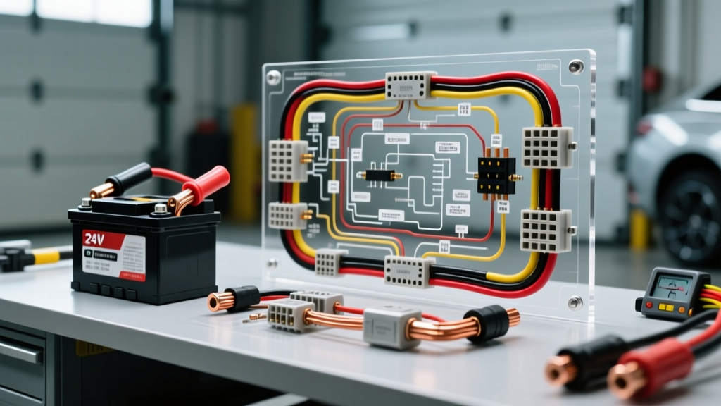
Understanding the 24V Series Architecture
When diagnosing heavy-duty commercial trucks, military platforms, or large marine vessels, interpreting a 24V battery wiring diagram requires a fundamental understanding of series circuits. Unlike standard 12V parallel systems, a true 24V system utilizes two 12V batteries (typically Group 31, 4D, or 8D) wired in series. The positive terminal of Battery A feeds the starter solenoid and main power distribution. The negative terminal of Battery A is linked to the positive terminal of Battery B via a heavy-gauge series interconnect cable. Finally, the negative terminal of Battery B is grounded to the chassis or engine block. This configuration doubles the voltage to 24V while maintaining the same amp-hour (Ah) capacity as a single battery. Because the system relies on a continuous, unbroken chain of high-current flow, a single high-resistance fault in the series link or ground path will cripple the entire electrical architecture.
Pre-Diagnostic Safety & Tool Requirements
Before tracing your 24V battery wiring diagram, gather the correct diagnostic equipment. Standard 12V test lights are useless and potentially dangerous here. You must use a Category III or IV Digital Multimeter (DMM) rated for at least 1000V DC to safely handle 24V transient spikes during cranking. Additionally, you will need a milli-ohm meter for precise resistance testing, a 12-ton hydraulic crimper for 2/0 AWG cable repairs, and a calibrated torque wrench. According to the SAE J563 standard for battery terminals, improper torque on battery posts is a leading cause of micro-arcing and terminal melting in high-amperage 24V applications.
The 24V Battery Wiring Diagram Troubleshooting Flow
Use this sequential decision tree to isolate faults. Do not skip phases, as a failing 12V accessory tap can mask as a bad battery cell.
Phase 1: Open-Circuit Voltage & State of Charge (SOC)
Disconnect the main chassis ground and the series link to isolate the batteries. Let them rest for 12 hours to eliminate surface charge. Measure each battery individually. A healthy 12V AGM or flooded lead-acid battery should read between 12.6V and 12.8V. If Battery A reads 12.7V and Battery B reads 11.9V, you have a cell imbalance. In a series circuit, the alternator pushes current through both batteries equally. If one battery is sulfated or has a dead cell, it will act as a resistor, causing the alternator to overcharge the healthy battery while the weak battery remains undercharged. Replace batteries in matched pairs; never mix ages or chemistries in a 24V bank.
Phase 2: The Series Link Voltage Drop Test
The inter-battery series link is the most abused cable in any 24V battery wiring diagram. It is often routed tightly across battery boxes, subjected to acid spills, and ignored during maintenance. Reconnect the series link (typically 1/0 AWG or 2/0 AWG red or black cable with heat-shrink sealing). Set your DMM to DC Volts. Place the red probe on the negative post of Battery A and the black probe on the positive post of Battery B. Have an assistant crank the engine. As per Fluke Corporation's voltage drop guidelines, any reading above 0.1V across this cable and its terminals indicates excessive resistance. If you read 0.5V or higher, the hydraulic crimp on the ring terminal is likely failing internally, or galvanic corrosion has formed between the copper strand and the lead-clad terminal.
Phase 3: Ground Path & Starter Solenoid Verification
Move to the main ground path. Place your DMM's red probe on the negative post of Battery B and the black probe on a clean, bare metal point on the engine block (not the starter housing). Crank the engine. A voltage drop greater than 0.15V indicates a compromised chassis ground. In heavy-duty applications, the ground cable (usually black, 2/0 AWG) must be terminated with a 3/8-inch ring terminal and bolted directly to the engine block with a star washer to bite through paint and corrosion. Torque this connection to 25 ft-lbs. If the ground is solid, test the positive feed to the starter solenoid. A drop greater than 0.2V on the positive side warrants replacing the main 24V positive cable or cleaning the battery disconnect switch contacts.
12V Accessory Taps & Battery Equalizer Diagnostics
The most catastrophic mistake made by aftermarket installers is pulling 12V directly from the center tap (the series link between Battery A and Battery B) to run radios, lights, or HVAC fans. This creates a parallel 12V draw on only half of the 24V series bank. The result is severe unbalancing: Battery A is constantly drained, while Battery B is constantly overcharged by the 24V alternator. Modern 24V wiring diagrams utilize a DC-DC Battery Equalizer (a heavy-duty step-down converter). The equalizer connects to the full 24V bank and outputs a regulated 12V/24V split, ensuring both batteries share the accessory load equally. If your diagnostic flow reveals that Battery A consistently tests lower in specific gravity or voltage than Battery B, immediately trace the orange or yellow 12V accessory wires. Verify they are routed to the equalizer's 12V output terminal, not the center series link. Check the equalizer's internal fuses and verify its input voltage is exactly 24V under load.
Alternator Ripple & Diode Failure in 24V Systems
A 24V alternator utilizes a full-wave bridge rectifier with six diodes to convert AC stator output to DC. If one or more diodes fail, AC ripple voltage is introduced into the 24V battery wiring diagram. This ripple causes rapid battery heating, accelerated water loss in flooded cells, and erratic behavior in the vehicle's ECM. To test for alternator ripple, switch your DMM to AC Volts. Place the probes across the main 24V positive and negative terminals while the engine is running at 1500 RPM with the headlights on. A healthy 24V alternator should produce less than 0.05V AC (50mV). If you read 0.2V AC or higher, the alternator rectifier assembly has failed. Do not ignore this; the AC ripple will destroy the battery equalizer and sensitive 12V telemetry modules within weeks.
Heavy-Duty 24V Cable Specification & Torque Chart
When repairing or upgrading a 24V battery wiring diagram, adherence to AWG sizing and terminal torque specifications is non-negotiable. Undersized cables will overheat during the 1000+ amp draw of a 24V starter motor engagement.
| Application | Min AWG Size | Terminal Type | Bolt Size | Torque Spec |
|---|---|---|---|---|
| Main Starter Positive | 2/0 AWG | Copper Ring, Heat Shrink | 3/8'-16 | 12-15 ft-lbs |
| Series Interconnect Link | 1/0 AWG | Lead-Clad or Copper Ring | 5/16'-18 | 8-10 ft-lbs |
| Main Chassis Ground | 2/0 AWG | Copper Ring w/ Star Washer | 3/8'-16 | 20-25 ft-lbs |
| Equalizer 24V Input | 4 AWG | Standard Ring Terminal | 5/16'-18 | 8-10 ft-lbs |
| Equalizer 12V Output | 8 AWG | Fused Ring Terminal | 1/4'-20 | 5-7 ft-lbs |
Common Failure Modes & Corrective Actions
1. Battery Disconnect Switch Arcing: Heavy-duty trucks use a 24V master disconnect switch on the negative ground path. Over time, the internal copper contacts pit and arc, creating a 0.5V to 1.0V drop. Fix: Bypass the switch temporarily with a jumper cable. If cranking speed returns to normal, replace the rotary disconnect switch. Never attempt to clean pitted internal contacts.
2. Mechanical Lug Compression Failures: Many technicians use a hammer and punch or a cheap mechanical ratchet crimper to attach 2/0 AWG lugs. These methods leave voids inside the terminal barrel, allowing acid fumes to wick into the copper strands via capillary action, turning the wire green and brittle. Fix: Cut the cable back to clean, bright copper. Use a closed-barrel copper terminal and a 12-ton hydraulic crimper with the correct hexagonal die. Seal the barrel with adhesive-lined marine heat shrink to block corrosive gases.
3. Parasitic Draw on the 24V Side: If the vehicle sits for three days and the 24V bank is dead, you have a parasitic draw. Unlike 12V systems, a 24V draw is often caused by a failing 24V-to-12V inverter or a shorted engine heater grid relay. Fix: Pull the main 24V mega-fuses one by one while monitoring the current with a DC clamp meter capable of reading low amperage. Isolate the circuit, then inspect the specific relay or inverter for internal diode bleed.
By strictly following this troubleshooting flow and respecting the physical laws of series circuits, you can accurately diagnose and repair any 24V battery wiring diagram, ensuring maximum cranking power and electrical longevity for heavy-duty applications.