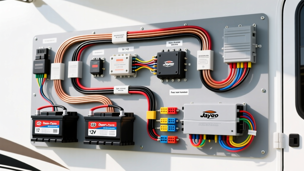
Decoding the OEM Jayco Battery Wiring Diagram
The factory Jayco battery wiring diagram is engineered for minimal compliance and baseline functionality, typically assuming a single Group 24 or Group 27 flooded lead-acid (FLA) battery. Whether you are upgrading a Jay Flight, White Hawk, or Eagle travel trailer, understanding the limitations of the original equipment manufacturer (OEM) wiring is the first step in designing a robust 12V DC power distribution system. From the factory, Jayco routes a 6 AWG or 4 AWG stranded copper positive cable (usually red, though older models may use black) from the battery tray on the A-frame to a 50A DC breaker or a rotary battery disconnect switch. The ground path relies on a white 6 AWG wire bonded to the chassis.
While adequate for a single 80Ah lead-acid battery powering a few LED lights and a water pump, this OEM wiring topology becomes a severe bottleneck when upgrading to high-capacity Lithium Iron Phosphate (LiFePO4) banks or adding a 2000W pure sine wave inverter. A 6 AWG wire over a 15-foot run carrying 50A will experience a voltage drop of approximately 0.6V. This drop starves the WFCO or Power Gear DC fuse panel, causing low-voltage disconnects and premature battery depletion. This guide compares the critical components required to overhaul your Jayco's electrical architecture, ensuring safe, high-current power distribution.
Battery Chemistry Selection: FLA vs. AGM vs. LiFePO4
Before altering your wiring diagram, you must select the appropriate battery chemistry. The physical wiring and charge profiles differ drastically between traditional lead-acid and modern lithium cells.
| Specification | Flooded Lead-Acid (FLA) | Absorbent Glass Mat (AGM) | Lithium Iron Phosphate (LiFePO4) |
|---|---|---|---|
| Usable Capacity | 50% (Deep cycle rated) | 50% - 80% | 90% - 100% |
| Bulk/Absorption Voltage | 14.4V - 14.8V | 14.2V - 14.6V | 14.2V - 14.6V (BMS Dependent) |
| Float Voltage | 13.2V - 13.4V | 13.2V - 13.4V | 13.5V - 13.6V (or BMS Sleep) |
| Internal Resistance | High (Limits high-amp draws) | Medium | Extremely Low (High surge capability) |
| BMS Requirement | None | None | Mandatory (LVD/HVD Protection) |
Wiring Implication: LiFePO4 batteries possess an exceptionally low internal resistance. In the event of a dead short, a lithium bank can deliver thousands of amps instantaneously before the internal Battery Management System (BMS) can sever the circuit. Therefore, upgrading to lithium mandates a complete revision of your overcurrent protection strategy, moving away from standard ANL fuses to high Ampere Interrupting Capacity (AIC) Class T fuses.
Converter/Charger Upgrades: WFCO vs. Progressive Dynamics
Most modern Jayco trailers are equipped with a WFCO 8955 (55-Amp) or 8935 (35-Amp) power distribution panel. The OEM WFCO converters are notorious for failing to trigger their 14.4V 'Boost' or 'Desulfation' mode when connected to a lithium battery, effectively stalling the charge at 13.6V. This leaves a LiFePO4 bank permanently undercharged at roughly 80% state-of-charge (SOC).
Component Comparison: OEM vs. Lithium-Specific Converters
- OEM WFCO 8955: Outputs a maximum of 14.4V only after 30+ hours of continuous low-load current detection. Unsuitable for LiFePO4. Requires complex wiring bypasses or manual boost switches to force a full charge.
- Progressive Dynamics PD4655LIV: A 55-Amp lithium-specific converter that outputs a hardwired, continuous 14.4V. According to Progressive Dynamics technical documentation, the LIV series eliminates the need for complex BMS communication wiring, relying on a fixed voltage profile that safely tops off lithium cells without triggering high-voltage disconnects (HVD).
Wiring the PD4655LIV: When swapping the WFCO deck for a Progressive Dynamics unit, the 120V AC shore power wiring (Black/Hot, White/Neutral, Green/Ground) remains identical. However, on the 12V DC side, you must verify the polarity of the main distribution busbars. The OEM Jayco diagram routes the Red 12V+ cable to the upper busbar and the White 12V- ground cable to the lower busbar. Ensure the main 50A DC breaker on the positive line is retained and placed within 18 inches of the battery terminal to comply with RVIA and NFPA 1192 fire safety standards.
Overcurrent Protection: Selecting the Right Fuse Topology
When redesigning your Jayco battery wiring diagram for a 200Ah+ lithium bank, selecting the correct main battery fuse is critical for preventing catastrophic thermal events.
- ANL Fuses (OEM Standard): Rated for 10,000 AIC at 32V DC. Adequate for lead-acid batteries but dangerous for large lithium banks. A lithium short-circuit can exceed 10,000 amps, potentially causing the ANL fuse to arc internally rather than extinguish the fault.
- Class T Fuses (Recommended Upgrade): Rated for 20,000 AIC at 125V DC. Class T fuses (such as the Blue Sea Systems 5112 series) feature a fast-blow ceramic core that safely extinguishes massive lithium surge currents. They must be installed on the positive cable within 7 inches of the battery terminal.
- MRBF (Marine/RV Battery Fuses): Mount directly to the battery post. While convenient for tight A-frame battery boxes, they are limited to 10,000 AIC and are best reserved for secondary accessory circuits (e.g., solar charge controllers or DC-DC chargers) rather than the main inverter trunk line.
Solar Integration: PWM vs. MPPT Charge Controllers
Jayco's OEM 'Solar Prep' packages typically feature a Zamp or Furrion roof port wired directly to the battery bank via 10 AWG or 12 AWG PV wire, terminating at a basic 10A PWM controller. PWM controllers clamp the solar panel voltage to match the battery voltage, wasting up to 30% of the panel's potential wattage.
MPPT Upgrade Path: Upgrading to a Victron SmartSolar MPPT 100/30 requires altering the roof-to-battery wiring diagram. MPPT controllers act as DC-DC buck converters, requiring the solar array to be wired in series (higher voltage, lower current) to maximize efficiency. You must reroute 8 AWG pure copper wire from the roof gland to the MPPT controller, and then use 6 AWG wire from the controller's load/battery terminals to the main busbar. Always wire the MPPT controller to the battery before connecting the solar panels to prevent frying the controller's logic board.
The RV 'Big 3' Wiring Upgrade Protocol
Borrowing from automotive high-current audio upgrades, the RV equivalent of the 'Big 3' involves replacing the three critical current paths to eliminate voltage drop and ground loops.
- Battery Positive to DC Busbar/Inverter: Replace OEM 6 AWG with 1/0 AWG or 2/0 AWG SAE J1127 compliant pure copper stranded wire. As noted in SAE J1127 battery cable specifications, pure copper offers superior ampacity and vibration resistance compared to copper-clad aluminum (CCA) alternatives.
- Battery Negative to Chassis Ground: Run a dedicated 1/0 AWG white ground cable directly from the battery negative terminal to a clean, bare-metal point on the main chassis frame. Use a stainless steel bolt and star washer to bite through the factory powder coating.
- Chassis Ground to DC Distribution Panel: Ensure the WFCO or Progressive Dynamics negative busbar is bonded to the chassis with a minimum 4 AWG wire to prevent 12V DC ground loops, which cause flickering LED lights and erratic water pump operation.
Termination, Crimping, and Torque Specifications
High-current DC wiring fails most frequently at the termination points due to galvanic corrosion and thermal expansion. Never use solder on high-amp battery cables; solder wicks into the wire strands, creating a rigid point that snaps under road vibration. Instead, use closed-end, adhesive-lined heat shrink ring terminals. Crimp using a hydraulic hex-crimper to ensure a gas-tight mechanical bond.
When terminating on LiFePO4 M8 threaded posts, torque specifications are paramount. The internal busbars of lithium cells are often soft aluminum or copper. Over-tightening will strip the threads or crack the cell casing. Use a calibrated inch-pound torque wrench set to 9 to 11 ft-lbs (108 to 132 in-lbs) for 5/16" or M8 terminal nuts. Apply a thin layer of di-electric grease or No-Ox-Id A-Special to the terminals post-torque to prevent moisture ingress and oxidation on the A-frame.