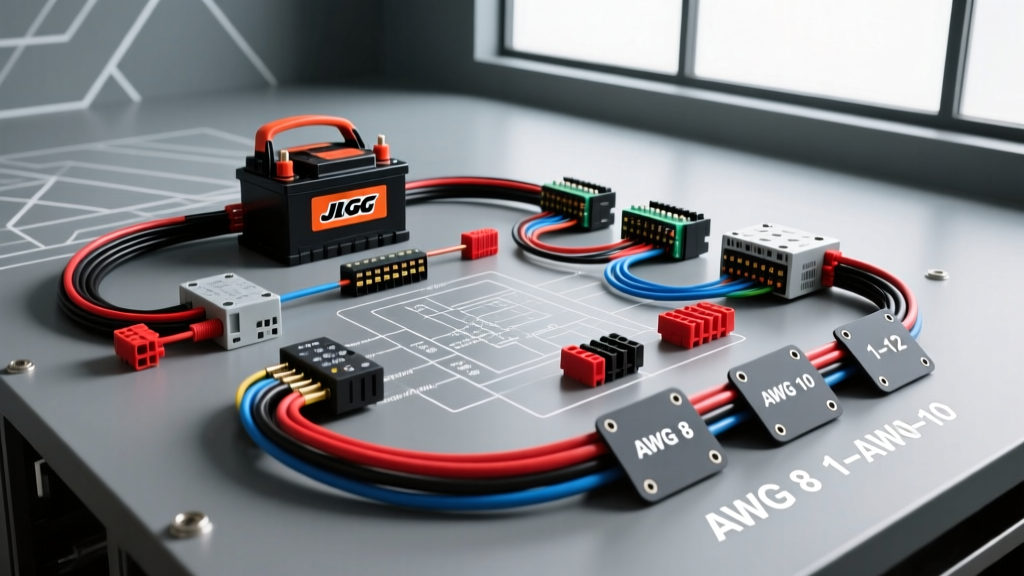
JLG 1930ES 24V DC Electrical Architecture Overview
The JLG 1930ES electric scissor lift relies on a robust 24V DC electrical architecture to power its drive motors, hydraulic pump, and control systems. Unlike standard 12V automotive applications, aerial work platforms (AWPs) demand sustained high-current delivery without excessive voltage sag. Understanding the JLG 1930ES battery wiring diagram is critical for technicians performing maintenance, troubleshooting drive faults, or executing battery bank replacements. This technical specification reference details the exact AWG requirements, pin configurations, torque specifications, and routing protocols necessary to maintain the integrity of the 1930ES power distribution system.
Battery Bank Configuration & Interconnect Specifications
The 1930ES utilizes a 24V nominal system, typically achieved by wiring four 6V deep-cycle flooded lead-acid batteries (such as the Trojan T-105 or equivalent 225Ah C20 rated cells) in series. Alternatively, some modernized fleets use two 12V AGM or Lithium Iron Phosphate (LiFePO4) batteries in series. When wiring the 6V series bank, the interconnect cables must handle the full system amperage, which can peak upwards of 350A during drive motor stall conditions or simultaneous hydraulic lifting.
According to the SAE J1128 Low Tension Battery Cable Standard, the minimum acceptable wire gauge for these interconnects is 2 AWG, though 1/0 AWG is highly recommended to minimize I²R (current squared times resistance) heat generation and voltage drop over the physical distance between battery trays. Using undersized cables leads to premature insulation melting and chronic undercharging of the rear batteries in the series loop.
Battery Interconnect & Main Feed Specifications
| Circuit Function | Wire Gauge (AWG) | OEM Color Code | Terminal Torque Spec | Overcurrent Protection |
|---|---|---|---|---|
| Battery Interconnects (Series) | 1/0 AWG Flex | Red / Black | 11-15 Nm (95-130 in-lbs) | None (Internal Bank) |
| Main Positive Feed to Contactor | 1/0 AWG SGX | Red | 15-20 Nm (130-175 in-lbs) | 250A ANL / Class T Fuse |
| Contactor Coil Control | 14 AWG THHN | Orange | N/A (Spade/DT) | 10A Blade Fuse |
| Charger Receptacle Feed | 6 AWG SGX | White / Black | 5-7 Nm (45-60 in-lbs) | 60A DC Breaker |
Main Power Distribution & Contactor Wiring
Power exits the battery bank via the main positive feed (typically 1/0 AWG Red wire) and routes to the main battery disconnect switch, followed by the primary high-current contactor (often an Albright SW200 or Trombetta equivalent). The contactor acts as the master relay for the drive and hydraulic systems.
Contactor Coil Circuit: The contactor coil requires a 24V DC signal to close the main high-current contacts. This control circuit utilizes 14 AWG or 12 AWG wire. The positive coil terminal receives switched 24V from the key switch and emergency stop (E-Stop) relay loop. The negative coil terminal routes to the chassis ground.
Pre-Charge Circuit: To prevent the main contactor contacts from welding together due to inrush current charging the motor controller’s large electrolytic capacitors, a pre-charge resistor (typically 47 to 100 Ohms, 50W) is wired in parallel with the main contactor or via a secondary delay relay. If the JLG 1930ES exhibits a "welded contactor" failure mode (where the machine remains powered on even after turning the key off), the pre-charge circuit or the main contactor contacts must be inspected for severe pitting.
Motor Controller & Drive Motor Wiring
The drive system is managed by a sophisticated motor controller (commonly a Curtis 1200-series or Sevcon Gen4 AC/DC controller). The Curtis Instruments Motor Controller Documentation dictates strict adherence to phase and power cable separation to prevent Electromagnetic Interference (EMI).
- B+ and B- Terminals: 1/0 AWG flexible stranded copper (SAE J1128 Type SGX) is used for the main battery positive (B+) and battery negative (B-) connections to the controller.
- Motor Phase Cables: For AC drive motors, three phase cables (U, V, W) are required. These are typically 2 AWG or 1 AWG and must be routed at least 4 inches away from low-voltage signal wires to prevent induced voltage spikes from causing controller logic faults.
- Signal & Logic Harness: The controller’s logic board is powered via a dedicated 24V input (often a 14 AWG Orange or Yellow wire) protected by a 10A inline blade fuse. This circuit must be connected to a clean, switched 24V source, not directly to the battery terminals, to ensure the controller shuts down completely and does not drain the battery bank via parasitic draw.
Signal Harness & EMI Mitigation Protocols
The JLG 1930ES utilizes proportional Hall-effect joysticks for drive and lift functions. These sensors output a 0.5V to 4.5V analog signal to the motor controller. If the battery power cables (carrying 300A+ pulsed DC current) are routed parallel to these signal wires without adequate separation, the magnetic field generated by the high-current cables will induce voltage spikes in the signal lines. This results in 'ghost' inputs, where the machine creeps or lifts without operator input.
To prevent this, the wiring diagram mandates a minimum 4-inch lateral separation between high-current power distribution harnesses and low-voltage signal harnesses. Where crossing is unavoidable, cables must intersect at a strict 90-degree angle. Furthermore, all analog signal wires must be routed using shielded twisted-pair (STP) cable, with the shield drain wire grounded exclusively at the controller end to prevent ground loops.
Charging Circuit & Anderson Connector Pinout
The 1930ES battery charging circuit relies on an external or onboard high-frequency smart charger. The physical connection to the machine is typically facilitated by an Anderson SB175 or SB50 connector.
Anderson SB175 Pinout & Wiring:
- Pin 1 (Positive): Connected to the battery bank positive via a 6 AWG or 8 AWG wire, protected by a 50A or 60A DC breaker.
- Pin 2 (Negative): Connected directly to the main negative battery post or a dedicated high-current ground busbar.
It is critical to verify the polarity of the Anderson connector. Reversing the polarity during aftermarket harness repairs will instantly destroy the onboard charger’s rectifier diodes and potentially fry the motor controller’s logic board. Always use a multimeter to verify Pin 1 is B+ relative to the chassis before plugging in the charger.
Ground Routing & Chassis Bonding Protocols
Proper grounding is the most frequently overlooked aspect of the JLG 1930ES wiring diagram. The scissor lift’s chassis serves as the common ground return for the hydraulic pump motor, steering valves, and platform control boxes. Referencing the JLG Industries Service Manual Repository, technicians must adhere to the following grounding protocols:
- Star Grounding: All low-current sensor grounds and logic grounds should be routed to a central star ground point to prevent ground loops, which can cause erratic behavior in the proportional control joysticks.
- High-Current Grounds: The motor controller B- cable and the main battery negative cable must terminate directly to a dedicated, unpainted steel chassis boss or a heavy-duty copper ground busbar.
- Surface Preparation: Any chassis ground point must be sanded down to bare, shiny metal. After securing the lug with a Grade 8 bolt and a star washer (to bite through any micro-corrosion), the connection must be coated with No-Ox-Id A-Special or a similar conductive anti-oxidant paste to prevent galvanic corrosion in outdoor or wash-down environments.
Diagnostic Decision Tree: Voltage Drop & Failure Modes
When troubleshooting electrical faults on the 1930ES, never rely solely on static voltage readings. A battery bank may read 25.4V at rest but drop to 16V under load if a high-resistance fault exists. Perform a dynamic voltage drop test across the entire battery wiring harness.
- Symptom: Machine clicks but drive motors do not engage.
Cause: High resistance at the main contactor or battery interconnects.
Fix: Place multimeter probes across the main contactor terminals while attempting to drive. A voltage drop greater than 0.1V indicates pitted internal contacts requiring contactor replacement. - Symptom: Erratic hydraulic lift functions or joystick drifting.
Cause: Ground loop or voltage drop in the 14 AWG logic ground wire.
Fix: Measure voltage drop between the controller logic ground pin and the main battery negative post under load. If >0.05V, re-route the logic ground directly to the battery negative terminal. - Symptom: Batteries boiling or charger failing to terminate.
Cause: Incorrect battery series wiring (e.g., creating a 12V loop instead of 24V) or a failed cell causing the charger to remain in bulk mode.
Fix: Verify interconnect wiring against the JLG 1930ES battery wiring diagram. Load test each 6V battery individually; replace the entire bank if one cell is more than 15% out of balance.