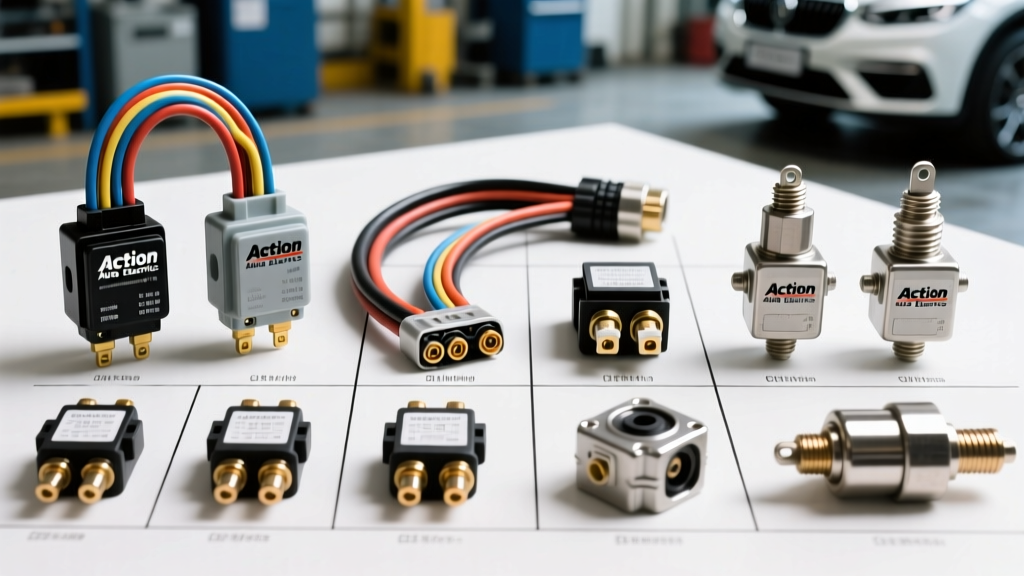
Introduction to High-Current Automotive Architectures
When modifying a vehicle for off-road use, towing, or auxiliary equipment integration, the factory electrical architecture is rarely sufficient. Standard OEM wiring harnesses and switching components are engineered with strict cost and weight constraints, typically supporting only the baseline electrical loads required for factory options. This is where specialized aftermarket suppliers step in. In this comprehensive product comparison and selection guide, we evaluate Action Auto Electrics heavy-duty components against standard OEM equivalents. We will break down the technical specifications of their relays, wiring looms, and high-amp solenoids to help you design reliable, high-current circuits that resist thermal degradation and voltage drop.
Relay Selection: ISO Mini vs. Action Auto Electrics Sealed Heavy-Duty
The standard 5-pin ISO mini relay (often referred to as a Bosch-style relay) is the backbone of most OEM automotive switching circuits. These relays are typically rated for 30A to 40A on the switched contacts (Pins 30 and 87) and feature a coil resistance between 70 and 90 ohms, drawing approximately 150mA at 12.6V. While adequate for standard lighting or fuel pump circuits, they fall short in high-vibration, high-temperature, or high-draw environments.
Action Auto Electrics offers a line of sealed, heavy-duty 50A and 70A relays designed for harsh engine bay and undercarriage environments. Unlike standard unsealed ISO relays, these units feature epoxy-potted internals and integrated weather-sealed connector housings. The pin configuration remains standard (Pin 30 for common power, Pin 87 for normally open output, Pin 85 for coil ground, and Pin 86 for coil trigger), but the internal contact materials utilize silver tin oxide (AgSnO2) rather than standard silver nickel. AgSnO2 provides superior resistance to contact welding and arc erosion when switching highly inductive loads like electric winches or air compressors.
Coil Suppression and ECU Protection
When driving a relay coil directly from a modern Body Control Module (BCM) or Powertrain Control Module (PCM), voltage spikes generated by the collapsing magnetic field (flyback voltage) can destroy sensitive solid-state drivers. Standard OEM relays often lack internal suppression. Action Auto Electrics heavy-duty relays frequently incorporate internal flyback diodes or suppression resistors across Pins 85 and 86. When selecting a relay for an ECU-triggered circuit, always verify the presence of this suppression. If using a non-suppressed Action relay, you must install an external 1N4004 diode in reverse bias across the trigger wires to protect the vehicle's CAN-bus modules.
Wiring Harnesses: PVC vs. Cross-Linked Polyethylene (XLPE)
The insulation material of your wiring loom is just as critical as the copper gauge. Standard OEM and cheap aftermarket harnesses often use Polyvinyl Chloride (PVC) insulation. PVC is rated for continuous temperatures up to 105°C and becomes brittle when exposed to prolonged UV light and engine bay heat cycles.
Action Auto Electrics premium harnesses utilize Cross-Linked Polyethylene (XLPE) insulation, specifically conforming to the SAE J1128 Standard for Low Tension Primary Cable. Within this standard, you will typically encounter GXL (General Cross-Linked) and TXL (Thin-wall Cross-Linked) wire. GXL features a standard wall thickness and is rated for continuous operation at 125°C, making it ideal for routing near exhaust manifolds or turbochargers. TXL offers a thinner wall for weight savings and tighter bend radii in complex dash harnesses, while maintaining the same thermal and chemical resistance to automotive fluids like brake fluid and synthetic oils.
Terminal Crimping and Sealed Connectors
A high-quality wire is useless if the termination point introduces resistance. Action Auto Electrics harness assemblies utilize Delphi Weather-Pack Sealed Connector Systems. These connectors feature silicone rubber seals that prevent moisture ingress, which is critical for exterior lighting and winch circuits. When assembling these connectors, the open-barrel terminal must be crimped using a specialized tool that forms both the conductor crimp (over the bare copper strands) and the insulation crimp (over the wire jacket and silicone seal). A proper crimp should exhibit a tensile pull-strength exceeding the wire's yield point, ensuring the connection will not fail under heavy vibration.
High-Amp Solenoids: Intermittent vs. Continuous Duty
Solenoids are essentially heavy-duty relays used for currents exceeding 100A, such as starter motor circuits, glow plug rails, and electric winches. A common and catastrophic mistake in custom automotive wiring is using an intermittent-duty solenoid for a continuous-duty application.
Standard OEM starter solenoids are intermittent-duty; they are designed to engage for 10 to 30 seconds at a time. Their copper coils are sized for high initial pull-in force, but they generate excessive heat during prolonged use. If used to power a continuous load like an electric air compressor or a high-amp cooling fan, the coil insulation will melt, causing an internal short to the steel casing. This typically results in the main fusible link blowing or, worse, an electrical fire. Action Auto Electrics continuous-duty solenoids are wound with heavier gauge copper wire and feature higher coil resistance. This reduces the holding current and minimizes thermal buildup, allowing them to operate safely at a 100% duty cycle without thermal runaway.
Component Specification Comparison Chart
| Component Type | Standard OEM Specification | Action Auto Electrics Heavy-Duty Spec | Recommended Application |
|---|---|---|---|
| ISO Mini Relay | 30A / 40A, AgNi Contacts, Unsealed | 50A / 70A, AgSnO2 Contacts, Epoxy Potted | Off-road LED bars, auxiliary fuel pumps |
| Primary Wire (10 AWG) | PVC Insulation, 105°C Rating | GXL (XLPE) Insulation, 125°C Rating | Engine bay routing, high-heat zones |
| High-Amp Solenoid | Intermittent Duty, 150A Peak | Continuous Duty, 200A Peak, Copper Coil | Winch control, glow plug rails, AC compressors |
| Connectors | Standard Spade / Unsealed Push-on | Weather-Pack 280 Series, Silicone Sealed | Exterior lighting, undercarriage sensors |
Application Guide: Wiring an Auxiliary Electric Air Compressor
To illustrate the proper selection and integration of these components, let us outline the wiring architecture for a 12V auxiliary air compressor drawing 45A under peak load. Because this draw exceeds the capacity of standard ISO mini relays and factory switches, we must utilize a heavy-duty switching circuit.
- Power Feed: Run an 8 AWG (8.37mm²) GXL wire directly from the positive battery terminal to a 60A ANL fuse, then to Pin 30 of the Action Auto Electrics 70A sealed relay. 8 AWG is selected over 10 AWG to minimize voltage drop over the long run from the battery to the rear of the vehicle.
- Switched Output: Connect Pin 87 of the relay to the compressor's positive terminal using the same 8 AWG GXL wire. Ground the compressor chassis directly to the vehicle frame using a dedicated 8 AWG ground strap, ensuring bare metal contact by removing any paint or powder coating.
- Trigger Circuit: Use 14 AWG TXL wire for the relay coil. Connect Pin 85 to a clean chassis ground. Connect Pin 86 to a low-amp dashboard toggle switch, which is fed by a 10A fused ignition-switched 12V source. This ensures the compressor cannot be left running when the vehicle is turned off, preventing battery drain.
- Suppression: If the chosen Action relay does not feature an internal diode, solder a 1N5408 flyback diode across Pins 85 and 86, with the cathode stripe facing Pin 86 (the positive trigger side).
Troubleshooting Voltage Drop and Thermal Issues
Even with premium components, poor installation can lead to system failure. The most common issue in high-amp aftermarket circuits is excessive voltage drop. According to Bosch Automotive Relays and Switching Technology guidelines, the maximum acceptable voltage drop across a closed relay contact is 0.2V at rated load. If your compressor is running slowly or drawing excessive amperage, perform a voltage drop test using a digital multimeter.
Place the multimeter probes directly on the relay's Pin 30 input wire and Pin 87 output wire while the circuit is under load. A reading above 0.2V indicates internal contact degradation or a poor terminal crimp at the relay plug. Additionally, check the ground circuit by measuring the voltage drop between the compressor casing and the negative battery terminal. A voltage drop greater than 0.1V on the ground side indicates a corroded chassis ground point, which forces the electrical system to seek alternative paths to ground, potentially backfeeding through sensitive CAN-bus wiring and causing erratic ECU behavior.
By prioritizing cross-linked wire insulation, silver tin oxide relay contacts, and continuous-duty solenoids, builders can ensure their high-current automotive systems operate reliably under the most demanding conditions, far exceeding the lifespan of standard OEM components.