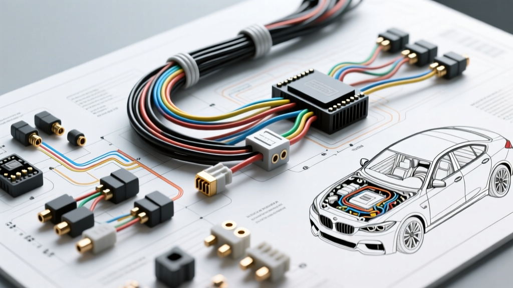
The Philosophy of Systematic Electrical Diagnostics
When dealing with complex automotive electrical faults, guesswork is the enemy of efficiency. The methodology championed by elite diagnostic centers—often referred to in industry circles as the Hyde Park Auto Electric troubleshooting flow—relies on empirical data, structured decision trees, and an unwavering adherence to Ohm's Law. Rather than swapping parts based on symptoms, this step-by-step approach isolates variables using voltage drop testing, oscilloscope waveform analysis, and quiescent current measurement.
Whether you are chasing a parasitic battery drain that kills a battery overnight, diagnosing a no-crank starter interlock, or tracing a Local Interconnect Network (LIN) bus fault on a modern smart alternator, the following diagnostic flows will guide you from symptom to root cause with surgical precision.
Phase 1: Parasitic Draw Isolation (The Voltage Drop Method)
The most common mistake amateur technicians make when diagnosing a parasitic draw is pulling fuses one by one with a multimeter in series. In modern CAN-bus architectures, removing a fuse drops power to a module, which then triggers a 'wake-up' sequence when the fuse is reinserted. This creates a false high-current reading and renders the test useless.
The Hyde Park methodology dictates using the voltage drop method across fuses while the vehicle is fully asleep. By measuring the millivolt (mV) drop across the blades of a fuse, you can calculate the current flowing through that specific circuit without ever breaking the connection.
Step-by-Step Parasitic Draw Flow
- Prepare the Vehicle: Close all doors, latch the hood and trunk (use a jumper wire on the latch switch if under-hood access is required), and remove the key. Wait for the CAN-bus to enter sleep mode (typically 20 to 45 minutes, depending on the OEM).
- Set the Multimeter: Switch your digital multimeter (DMM) to the DC millivolt (mV) scale.
- Test the Fuses: Place the DMM probes on the two exposed test points on the top of each mini/ATO fuse in the fuse box.
- Identify the Culprit: Any fuse showing a voltage drop higher than 0.10mV (100 microvolts) is passing current. Cross-reference the mV reading with the chart below to determine the exact amperage.
| Fuse Rating | 10mA (0.010A) | 25mA (0.025A) | 50mA (0.050A) | 100mA (0.100A) |
|---|---|---|---|---|
| 5 Amp | 0.7mV | 1.8mV | 3.5mV | 7.0mV |
| 10 Amp | 0.4mV | 1.0mV | 2.0mV | 4.0mV |
| 15 Amp | 0.3mV | 0.7mV | 1.4mV | 2.8mV |
| 20 Amp | 0.2mV | 0.5mV | 1.0mV | 2.0mV |
Note: Acceptable sleep-mode quiescent current for most modern vehicles is between 20mA and 50mA. If your total vehicle draw exceeds 50mA after the sleep timer expires, isolate the circuit with the highest mV drop and consult the OEM wiring diagram for module fault codes. For deeper CAN-bus sleep analysis, refer to the AutoShop 101 Electrical Circuits Guide.
Phase 2: No-Crank / Starter Circuit Decision Tree
A 'no-crank' condition is rarely a simple 'bad starter' scenario. Modern vehicles utilize immobilizers, Transmission Range (TR) sensors, and Body Control Modules (BCMs) to gate the starter solenoid trigger wire. The following flow isolates the mechanical, high-current, and logic-level faults.
Step 1: Global Battery Health & Cable Integrity
Before touching the starter, verify the high-current supply. A battery showing 12.6V at rest may still collapse under load due to internal sulfation.
- Test: Perform a cranking voltage drop test. Place the red probe on the battery positive post and the black probe on the starter B+ terminal.
- Specification: The voltage drop on the positive 2 AWG or 4 AWG cable must be less than 0.20V during cranking.
- Ground Side: Place the red probe on the battery negative post and the black probe on the starter casing. The drop must be less than 0.10V.
- Hardware Check: If testing a GM side-terminal battery, ensure the 3/8-16 UNC bolt is torqued to 11-15 Nm (95-130 in-lbs). Loose terminals cause micro-arcing that mimics a failing starter.
Step 2: Solenoid Trigger Wire ('S' Terminal) Analysis
If the high-current cables pass, move to the control circuit. The 'S' terminal typically receives 12V via a 16 AWG or 18 AWG trigger wire (often Yellow/Red or Purple, depending on the OEM).
- Test: Connect a test light or DMM to the 'S' terminal wire (back-probe the connector) and command a start.
- Result A (No Voltage): The fault is upstream. Check the ignition switch output, the clutch/brake pedal interlock switches, and the PCM/BCM starter relay control logic.
- Result B (12V Present, Solenoid Clicks but No Spin): The starter motor has an internal fault (e.g., worn carbon brushes, open armature winding, or a seized Bendix drive). Bench-test or replace the starter assembly.
Phase 3: Modern Alternator LIN-Bus Troubleshooting
Gone are the days of the simple 1-wire or 3-wire alternator with a basic 12V exciter circuit. Modern vehicles use Regulated Voltage Control (RVC) or Smart Charge systems, where the Powertrain Control Module (PCM) communicates with the alternator's internal voltage regulator via a Local Interconnect Network (LIN) bus. When a LIN-bus fault occurs, the alternator defaults to a base voltage (usually 13.5V) or stops charging entirely, triggering a battery warning light.
Identifying the LIN Wire
The LIN wire is typically an 18 AWG single-core conductor. Common OEM color codes include:
- General Motors (RVC): Red/White or Gray (PWM signal from ECM).
- Ford (Smart Charge): Yellow/Green (LIN data line).
- Chrysler/FCA: Dark Green/Orange.
Step-by-Step LIN-Bus Diagnostic Flow
- Visual Inspection: Check the alternator connector for corrosion, pushed-back pins, or chafing against the engine block. The LIN circuit is highly sensitive to resistance; even 5 ohms of corrosion can corrupt the PWM signal.
- Multimeter Baseline Test: With the engine running, back-probe the LIN wire. A standard DMM will show an average DC voltage between 7.0V and 11.0V. If you read a solid 12.0V or 0.0V, the PCM has lost communication or the wire is shorted to power/ground.
- Oscilloscope Waveform Analysis: To truly diagnose the LIN bus, connect an automotive oscilloscope (e.g., PicoScope). You should see a square-wave PWM signal toggling between 0V and 12V.
- Low Charge Demand: Duty cycle approx. 10% - 20%.
- High Charge Demand (e.g., cold battery, high electrical load): Duty cycle approx. 80% - 90%.
- Signal Dropout: If the waveform shows rounded edges or voltage spikes, suspect inductive interference from a failing ignition coil or a damaged wiring harness shield. For advanced waveform interpretation, consult the Pico Automotive Oscilloscope LIN-Bus Library.
| Oscilloscope Reading | DMM Average Voltage | Probable Root Cause |
|---|---|---|
| Flatline at 0V | 0.0V | Open circuit, broken 18 AWG wire, or failed PCM driver. |
| Flatline at 12V | 12.6V | Short to battery positive, or internal alternator regulator failure. |
| Noisy / Rounded Edges | Fluctuating 4V-9V | High resistance in connector, EMI from ignition coils. |
| Clean Square Wave | 7.5V - 10.5V | Normal operation; check battery internal resistance if undercharging. |
Essential Tools for the Hyde Park Methodology
Executing these step-by-step flows requires precision instruments. A standard $20 multimeter will not suffice for millivolt drop testing or PWM signal analysis. Your diagnostic arsenal must include:
- True-RMS Digital Multimeter: Capable of measuring down to 0.1mV (e.g., Fluke 88V Automotive DMM).
- Automotive Oscilloscope: Minimum 2-channel, 20MHz bandwidth for capturing LIN-bus and CAN-bus waveforms without aliasing.
- Fused Jumper Wires: 14 AWG and 16 AWG wires with inline 10A and 20A ATO fuses for safely bypassing relays and switches during logic testing.
- Thermal Imaging Camera: Invaluable for instantly locating high-resistance connections at the fuse box or battery terminals by detecting localized heat generation under load.
Conclusion: Trust the Data, Not the Symptoms
The core tenet of the Hyde Park Auto Electric troubleshooting flow is that electrical systems do not lie; they only respond to the physical constraints of voltage, current, and resistance. By systematically eliminating variables—starting with the power supply, moving through the control logic, and ending at the load component—you transform chaotic electrical gremlins into predictable, solvable equations. Always verify your repairs by re-running the initial baseline tests to ensure the circuit operates within OEM specifications. For comprehensive EMC and wiring standards, reference the SAE J1113 Electromagnetic Compatibility Standards to ensure your aftermarket repairs do not introduce signal noise into sensitive vehicle networks.