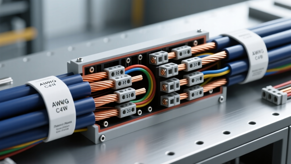
The Harbor Auto Electric Environment: SAE vs. ABYC Standards
Vehicles operating in harbor, dock, and shipyard environments face extreme electrical degradation due to saltwater aerosolization, high humidity, and galvanic corrosion. Standard automotive wiring, governed by SAE J1128, utilizes untinned copper that rapidly oxidizes and turns black when exposed to marine atmospheres. This oxidation increases resistance, causes severe voltage drop, and ultimately leads to starter circuit failure or alternator undercharging. To build a reliable harbor auto electric system, technicians must transition from standard automotive practices to marine-grade specifications outlined by the American Boat and Yacht Council (ABYC).
The core of harbor auto electric architecture relies on tinned copper wire, sealed connectors, and ignition-protected components. Unlike standard passenger vehicles, harbor service trucks, dock tractors, and marine patrol vehicles require electrical systems that can withstand continuous exposure to corrosive elements while meeting strict safety codes for operation near combustible marine fumes.
Tinned Copper AWG Specifications and Ampacity Charts
When sizing wire for harbor auto electric applications, you must reference the ABYC E-11 Standard rather than standard automotive charts. ABYC mandates that wire used in engine spaces must be rated for 105°C, whereas standard automotive wire is often rated for 85°C to 100°C. Furthermore, the tinning process slightly increases the overall diameter of the copper strands, which can marginally affect ampacity in tightly bundled harnesses.
Below is the technical specification chart for selecting the correct AWG size for primary DC power and starter circuits in harbor environments. Note that ABYC requires a 10% derating for bundles containing more than three current-carrying conductors.
| AWG Size | Stranding (Tinned) | Max Ampacity (Engine Space 105°C) | Max Ampacity (Non-Engine Space 105°C) | Typical Harbor Application |
|---|---|---|---|---|
| 10 AWG | 49/27 | 30A | 45A | Bilge pumps, dock lighting circuits |
| 8 AWG | 77/27 | 40A | 65A | Electric AC compressor clutches, winches |
| 6 AWG | 133/27 | 60A | 95A | Alternator B+ output (up to 60A units) |
| 4 AWG | 210/27 | 85A | 130A | High-output alternator feeds, battery banks |
| 2 AWG | 336/27 | 120A | 175A | Primary battery to starter motor feeds |
| 1/0 AWG | 532/27 | 160A | 230A | Heavy-duty dock tractor starter circuits |
ABYC Color Code Compliance: In harbor auto electric systems, DC positive conductors must be Yellow. The starting circuit positive should be Yellow with a Red stripe. DC negative and ground return conductors must be Yellow with a Black stripe. This contrasts sharply with standard automotive red/black conventions but is critical for avoiding catastrophic cross-wiring during harbor maintenance.
Ignition-Protected Alternators and Starter Circuits
Harbor environments often involve proximity to marine fuel vapors, bilge gases, and industrial solvents. Under USCG 33 CFR 183.410, electrical components installed in these environments must be ignition-protected. Standard automotive alternators and starter solenoids can arc internally, igniting surrounding fumes.
Marine Alternator Pinout and Conversion Specs
When upgrading a harbor service vehicle to an ignition-protected alternator (such as a marine-rated Delco 10SI or 12SI equivalent), the external wiring harness must be adapted. Marine alternators feature specialized spark arrestor screens on the intake and exhaust ports, and epoxy-potted stator windings to prevent moisture intrusion.
- Terminal 1 (Sense/Excite): Connect to the ignition switch via a 10 AWG tinned wire. Must include a 10-amp inline fuse. Voltage must read within 0.2V of battery base voltage during cranking.
- Terminal 2 (Voltage Sense): Must be routed directly to the positive battery post or the common positive bus bar using a minimum 8 AWG wire. Do not splice this into the alternator B+ post, as harbor voltage drops will cause severe overcharging.
- B+ Output Post: Torque the marine-grade stainless steel nut to exactly 120 in-lbs (10 ft-lbs). Use a 6 AWG or 4 AWG tinned cable with an adhesive-lined heat shrink terminal.
Sealed Connectors and Harness Routing
Standard push-on spade terminals and open-barrel crimps are strictly prohibited in harbor auto electric systems. Moisture wicking through capillary action will destroy a standard harness in under six months in a saltwater environment.
Approved Connector Architectures
- Deutsch DT Series: The gold standard for harbor sensor and actuator connections. Features a thermoplastic housing with silicone rear grommets. Requires solid copper core crimping and a specific extraction tool for service.
- TE Connectivity (Amp) Superseal 1.5: Ideal for high-vibration alternator and starter solenoid trigger wires. Must use the secondary locking wedge (TPA) to prevent pin back-out.
- Adhesive-Lined Heat Shrink: All crimped terminals must use dual-wall, polyolefin heat shrink with an inner melamine adhesive lining. When heated to 120°C, the adhesive melts and flows into the wire strands, creating a 100% waterproof seal that blocks saltwater wicking.
Diagnostic Decision Tree: Stray Current and Voltage Drop
Harbor vehicles frequently suffer from stray current corrosion and hidden voltage drops due to micro-fractures in oxidized wire strands. Use the following diagnostic sequence with a digital multimeter (DMM) set to DC Millivolts.
Step 1: The Starter Circuit Voltage Drop Test
- Action: Place DMM positive lead on battery positive post, negative lead on starter motor B+ terminal.
- Threshold: Crank engine. Reading must be < 0.50V total for the entire positive cable length.
- Failure Mode: If reading is > 0.50V, isolate the drop across each connection (battery terminal, fuse block, solenoid). Any single connection showing > 0.10V requires disassembly, wire brushing, and application of anhydrous dielectric grease.
Step 2: Alternator Ground Return Verification
- Action: Place DMM negative lead on battery negative post, positive lead on alternator casing (bare metal).
- Threshold: Run engine at 2000 RPM with high electrical load (AC compressor, dock lights). Reading must be < 0.10V.
- Failure Mode: Harbor environments cause rapid galvanic corrosion between the aluminum alternator casing and the cast-iron engine block. If voltage drop exceeds 0.10V, install a dedicated 8 AWG tinned copper ground strap directly from the alternator casing to the engine block or battery negative bus.
Step 3: Stray Current Leak Detection
When a harbor vehicle is docked or parked near saltwater, stray DC current can leak through the chassis into the water, causing rapid galvanic destruction of nearby marine infrastructure or the vehicle's own submerged components.
- Action: Disconnect the negative battery cable. Connect the DMM (set to 10A DC) in series between the negative battery post and the disconnected cable.
- Threshold: With all switches off, parasitic draw must be < 50mA (0.05A).
- Fix: If draw exceeds 50mA, pull fuses one by one. Common harbor culprits include corroded bilge pump float switches, unsealed aftermarket GPS trackers, and degraded electric AC compressor clutch relays. Install a heavy-duty marine battery disconnect switch (rated for 1000A cranking) to isolate the battery during long-term harbor storage.
Conclusion
Transitioning to a harbor auto electric standard is not merely an upgrade; it is a critical safety and reliability requirement for vehicles operating in marine environments. By adhering to ABYC wire sizing, utilizing tinned copper, enforcing ignition protection, and executing rigorous voltage drop diagnostics, fleet managers and technicians can ensure that harbor service vehicles remain operational despite the harshest saltwater conditions.