Introduction to Auto Electrical Systems Fundamentals
Whether you are restoring a classic muscle car, wiring auxiliary off-road lights, or diagnosing a parasitic draw on a daily driver, understanding the core principles of auto electrical systems is non-negotiable. Modern vehicles feature complex CAN-bus networks, LIN-bus modules, and multiplexed body control modules, but the underlying 12-volt DC architecture remains universally consistent. This beginner-friendly guide strips away the intimidation factor, focusing on the physical wiring, terminal standards, and circuit logic that form the backbone of every vehicle on the road.
The Core 12V Architecture: Power, Load, and Ground
Every functional circuit in auto electrical systems requires three fundamental elements: a power source, a load, and a return path to ground. The vehicle's 12V lead-acid or AGM battery provides the baseline chemical energy, maintaining a resting voltage of 12.6V. When the engine runs, the alternator takes over, supplying between 13.8V and 14.4V to power the vehicle's electronics while simultaneously recharging the battery.
The main charge wire connecting the alternator's B+ terminal to the battery's positive post is the highest-current cable in standard auto electrical systems. For a standard 100A to 150A alternator, this requires a minimum of 4 AWG stranded copper wire. For high-output alternators (200A+), upgrading to 2 AWG or 1/0 AWG welding cable is mandatory to prevent voltage drop and thermal degradation. Grounding is equally critical; the engine block must be tied to the chassis and battery negative using braided copper ground straps, typically 10 AWG or 8 AWG, to ensure the starter motor and ignition coils have a zero-resistance return path.
DIN 72552: The Universal Terminal Language
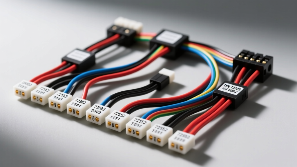
One of the most common mistakes beginners make when navigating auto electrical systems is relying solely on wire colors. Wire colors fade, get replaced, or vary wildly by manufacturer and model year. Instead, professionals rely on terminal designations. The DIN 72552 standard is a globally recognized numbering system for automotive electrical terminals, originally developed in Germany but now used by Bosch, Hella, and most global OEMs. Memorizing these codes will instantly demystify alternator pinouts, starter solenoids, and relay blocks.
| Terminal Code | Function | Common Application |
|---|---|---|
| 15 | Switched Ignition Power | Fuse box feeds, radio memory, ECU wake-up |
| 30 | Constant Battery Power | Direct battery feeds, horn relays, power seats |
| 31 | Ground (Earth) | Direct connection to chassis or battery negative |
| 50 | Starter Motor Control | Ignition switch to starter solenoid trigger |
| 85 / 86 | Relay Coil Terminals | Electromagnet winding inside a standard ISO relay |
| 87 / 87a | Relay Load Output | 87 is Normally Open (NO), 87a is Normally Closed (NC) |
For example, when testing an alternator's voltage regulator plug, you will often see Terminal 15 (ignition sense) and Terminal 30 (battery sense). If Terminal 15 loses power while the engine is running, the alternator may cease charging to protect the system.
Decoding Standard ISO Relays
Relays are the workhorses of auto electrical systems, allowing a low-current switch (like a dashboard headlight toggle) to control a high-current load (like 55W halogen bulbs) without melting the switch contacts. The standard Bosch-style 4-pin and 5-pin ISO mini relays are ubiquitous in automotive harnesses.
- Pin 30: Common power input. Connect directly to the battery via an inline fuse (e.g., 20A ATO fuse for a 30A relay).
- Pin 87: Normally Open (NO) output. Routes power to the load (e.g., fuel pump, cooling fan) only when the relay coil is energized.
- Pin 85: Relay coil ground. Usually tied to a clean chassis ground (Terminal 31).
- Pin 86: Relay coil power. Connected to the low-current trigger switch (Terminal 15 or a sensor ground-switch).
- Pin 87a: (5-pin only) Normally Closed (NC) output. Powers the load when the relay is off. Often used for headlight high/low beam switching or wiper park circuits.
Wire Gauge (AWG) and Color Coding Standards
Wire sizing in auto electrical systems follows the American Wire Gauge (AWG) standard, but it must be calculated based on both amperage and circuit length. A wire that is safe for 10 amps over a 2-foot run will experience dangerous voltage drop over a 15-foot run to a rear tail light. Always use stranded copper wire rated for automotive use (SAE J1128 or GXL/TXL cross-linked polyethylene insulation), which resists heat, oil, and vibration far better than solid-core household wire.
AWG Sizing Reference for Common 12V Loads
| Wire Gauge (AWG) | Max Amperage (Chassis Wiring) | Typical Automotive Application |
|---|---|---|
| 18 AWG | 5A - 7A | Dash illumination, ECU sensor signals, LED markers |
| 16 AWG | 8A - 10A | Horn circuits, interior dome lights, radio accessories |
| 14 AWG | 12A - 15A | Headlight circuits (H7/H11), power windows, wiper motors |
| 12 AWG | 16A - 20A | Blower motors, ABS module feeds, auxiliary 12V sockets |
| 10 AWG | 25A - 30A | Starter solenoid triggers, main EFI relay feeds, high-power fans |
| 8 AWG | 40A - 50A | High-output audio amplifiers, air suspension compressors |
Automotive Wire Color Conventions
While OEM wiring harnesses use highly specific color codes with tracer stripes (e.g., Black/White or Red/Yellow), aftermarket and repair wiring generally follows a universal convention to maintain sanity in auto electrical systems:
- Red: Constant 12V battery power (always fused at the source).
- Black or Brown: Ground / Earth return.
- Yellow: Switched 12V (Ignition / Accessory).
- Blue: Low-current trigger wires or relay coil feeds.
- Green/White: Sensor signals, data lines, or CAN-bus wiring.
Weather-Pack and Metri-Pack Connectors
Soldering and heat-shrinking are fine for permanent repairs, but modern auto electrical systems rely on sealed connectors to prevent moisture ingress and galvanic corrosion. The Weather-Pack (originally Packard/Delphi) and Metri-Pack series are the industry standards for under-hood and chassis wiring.
When crimping these terminals, the silicone weather seals are color-coded by wire gauge. Using the wrong seal will result in a loose connection that wicks water directly into the copper strands via capillary action. Red seals are used for 18-22 AWG wire, Yellow seals for 14-16 AWG, and Green or Clear seals for 10-12 AWG. Always use a dedicated open-barrel ratcheting crimper; standard pliers will deform the terminal and compromise the mechanical pull-out strength.
For high-vibration, high-temperature environments like fuel injector harnesses or transmission solenoid packs, Deutsch DT connectors are preferred. These utilize solid cylindrical pins and require specific cavity sizing (Size 16 for 14-16 AWG, Size 12 for 10-12 AWG) along with rear grommets and wedge locks to ensure the terminal cannot back out under extreme engine vibration.
Beginner Troubleshooting: Voltage Drop and Parasitic Draws
The most common failure in aging auto electrical systems is not a broken wire, but high resistance caused by corrosion. A multimeter's continuity beep function is useless for diagnosing high-resistance faults because it only requires a single strand of copper to complete the circuit. Instead, you must perform a voltage drop test under load.
- Set your multimeter to DC Volts.
- Turn the circuit ON (e.g., crank the starter or turn on the high-beam headlights) so current is flowing.
- Place the red probe on the battery positive post and the black probe on the load's power terminal.
- Read the voltage. A healthy power circuit should drop no more than 0.2V total across the entire length of the wire and all intermediate connections.
- Repeat on the ground side: Red probe on the load's ground terminal, black probe on the battery negative post. The acceptable drop here is even stricter: 0.05V to 0.1V.
If you measure a 1.5V drop on the ground side of a starter motor circuit, the starter is only seeing 11.1V instead of 12.6V, resulting in sluggish cranking. The fix is rarely a new starter; it is almost always cleaning the engine block ground strap or replacing a corroded battery terminal.
Another critical skill is testing for parasitic draws. When a vehicle sits, modules go to 'sleep'. To test, disconnect the negative battery terminal, set your multimeter to the 10A fused DC Amp setting, and place the meter in series between the negative post and the disconnected cable. Wait 20 minutes for all modules to sleep. A normal parasitic draw should be under 50mA (0.05A). If it reads higher, pull fuses one by one until the draw drops to isolate the offending circuit.
Authoritative Resources for Further Study
To deepen your understanding of auto electrical systems, consult the engineering standards and manuals that professionals use daily:
- SAE J1128: Low Tension Primary Cable - The definitive Society of Automotive Engineers standard for automotive wire insulation, temperature ratings, and stranded copper specifications.
- Bosch Automotive Electrics & Electronics - Bosch's technical documentation provides unparalleled insight into alternator regulation, DIN terminal logic, and ISO relay architectures.
- Haynes Automotive Electrical Manual - An excellent hands-on reference for tracing circuits, reading OEM wiring diagrams, and executing safe soldering and crimping procedures.
Mastering these fundamentals will transform auto electrical systems from a source of frustration into a logical, solvable puzzle. Always disconnect the battery negative terminal before cutting or splicing wires, and never bypass a blown fuse with a higher-amp rating.