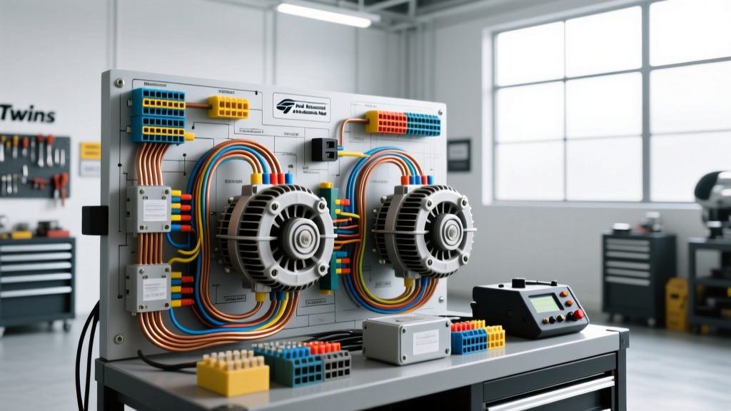
The Benchmark: Twins Auto Electrical and Mechanical Repair Methodologies
When benchmarking advanced diagnostic protocols in the automotive aftermarket, the methodologies employed by specialists like Twins Auto Electrical and Mechanical Repair provide a masterclass in bridging high-load mechanical demands with sensitive Controller Area Network (CAN-bus) and Pulse Width Modulation (PWM) electrical networks. Modern heavy-duty and high-performance vehicles frequently utilize 'twins' or dual-system architectures—most notably dual-alternator charging systems and twin-turbocharger electronic actuator circuits. Diagnosing these systems requires a departure from standard 12-volt parasitic draw testing, moving instead into high-amperage voltage drop analysis, thermal degradation mapping, and oscilloscope-based PWM duty cycle verification.
This technical specification reference outlines the exact wire gauges, pinout configurations, torque specifications, and diagnostic thresholds required to service complex dual-system electrical architectures, adhering to the rigorous standards expected of top-tier electrical and mechanical repair facilities.
Dual-Alternator High-Current Charging Architectures
In applications such as the Ford 6.7L Powerstroke or heavy-duty GM Duramax platforms, a single alternator cannot sustain the continuous 250+ ampere loads required by aftermarket PTOs, heavy winching, or extensive auxiliary lighting. Dual-alternator systems split this burden, but they introduce complex mechanical-electrical integration challenges. The primary and secondary alternators are not simply wired in parallel; they are managed independently by the Powertrain Control Module (PCM) to prevent voltage spikes and phase-mismatched ripple currents that can destroy sensitive CAN-bus transceivers.
According to SAE J1128 standards for low-tension primary cable, high-temperature engine bay environments require Cross-Linked Polyethylene (XLPE) insulation rather than standard PVC, which becomes brittle and cracks when exposed to continuous radiant heat exceeding 125°C (257°F).
Dual Alternator Wiring & Terminal Specification Chart
| Circuit Function | AWG / mm² | Wire Color Code | Terminal Type | Torque Spec (Stud/Nut) |
|---|---|---|---|---|
| Primary B+ Output | 1/0 AWG (53.5 mm²) | Red (XLPE) | M10 Ring Terminal | 25 Nm (18 lb-ft) |
| Secondary B+ Output | 2 AWG (33.6 mm²) | Red (XLPE) | M8 Ring Terminal | 12 Nm (9 lb-ft) |
| PCM Sense / IAT | 18 AWG (0.8 mm²) | Light Green/Orange | Deutsch DT 2-Pin | N/A (Click-Lock) |
| Alternator A (Field) | 16 AWG (1.3 mm²) | Violet/Orange | Weatherpack 150 | N/A |
| Alternator B (PWM) | 16 AWG (1.3 mm²) | White/Red | Weatherpack 150 | N/A |
PCM PWM Control Circuit Pinouts & Oscilloscope Verification
The PCM regulates the secondary alternator via a PWM signal on the 'B' circuit. A common failure mode misdiagnosed as a mechanical bearing failure is actually a degraded PWM signal causing the voltage regulator to rapidly cycle the field coil, leading to severe acoustic whining and premature brush wear. Using a digital storage oscilloscope (DSO), technicians must verify the PWM frequency and duty cycle at the alternator connector.
- Target Frequency: 125 Hz to 150 Hz (varies by OEM).
- Duty Cycle (Idle/No Load): 10% to 15% (approx. 13.2V system target).
- Duty Cycle (High Load/Thermal): 85% to 90% (approx. 14.8V system target).
- Failure Mode: If the DSO shows a flat 12V line instead of a square wave, the PCM driver has failed or the control wire (Violet/Orange) has shorted to B+ voltage, permanently maxing out the alternator output and boiling the battery electrolyte.
Twin-Turbo Electronic Wastegate & Boost Solenoid Integration
Twin-turbo configurations rely on precise electronic boost control solenoids (EBCS) and variable geometry turbocharger (VGT) actuators. The mechanical repair of a turbocharger is incomplete without verifying the electrical actuation circuits. A stuck VGT vane is often blamed on carbon buildup (a mechanical issue) when the root cause is a 5-volt reference short in the actuator harness.
EBCS Diagnostic Decision Tree
- Symptom: Under-boost condition, DTC P0299 (Turbocharger/Supercharger Underboost).
- Step 1: Coil Resistance Test. Disconnect the EBCS. Measure resistance across the two terminals. Specification: 33 Ω ± 2 Ω at 20°C (68°F). If reading is infinite (OL), the internal solenoid coil is open. Replace solenoid.
- Step 2: Insulation Breakdown Test. Apply 500V DC using a megohmmeter between either terminal and the solenoid housing. Specification: >10 MΩ. If lower, the coil is shorting to the chassis under high-vibration mechanical conditions.
- Step 3: PCM Driver Verification. Connect a DSO to the PCM ground control wire (typically Brown/Yellow). Command a WOT (Wide Open Throttle) run. The DSO should show a 300+ Hz square wave with a varying duty cycle peaking at 80-90% under maximum boost demand.
Mechanical-Electrical Grounding Standards & Voltage Drop
A core tenet of the Twins Auto Electrical and Mechanical repair philosophy is that 80% of all electrical anomalies in dual-system vehicles are caused by mechanical grounding failures. High-amperage components like starter motors and secondary alternators require massive current return paths. When engine components are removed and reinstalled during mechanical repairs, ground straps are often reinstalled over painted surfaces, powder-coated brackets, or without the requisite star washers.
High-Current Voltage Drop Testing Protocol
Do not use an ohmmeter to test ground circuits; an ohmmeter uses less than 10 milliamps of test current, which will easily pass through a single strand of copper wire or a layer of conductive carbon. You must test the circuit under load using a Digital Multimeter (DMM) in DC Millivolt mode.
- Test Point A: DMM Red lead on the Alternator case (bare metal).
- Test Point B: DMM Black lead on the negative battery post (not the clamp, the post itself).
- Load Application: Start the engine, turn on high-beam headlights, rear defroster, and AC blower to max.
- Maximum Allowable Voltage Drop: 0.05V (50mV) across any single mechanical ground junction. A reading of 0.15V or higher indicates severe mechanical corrosion or improper torque on the ground stud.
All M8 and M10 ground studs on the engine block must be cleaned to bare metal using a 3M Roloc bristle disc, treated with a conductive anti-oxidant compound (such as NO-OX-ID A-Special), and torqued to 22 Nm. For further reading on electrical testing standards, refer to the diagnostic guidelines published by the National Institute for Automotive Service Excellence (ASE).
Wire Insulation & Thermal Degradation in Twin-System Bays
The mechanical layout of twin-turbo and dual-alternator engines creates extreme localized heat zones. Standard automotive primary wire (GXL or TXL) may suffice for the cabin, but engine bay harnesses routed near exhaust manifolds and turbocharger housings require specialized insulation. SAE J1113 outlines the electromagnetic and thermal resilience required for these circuits.
Technicians must utilize PTFE (Teflon) or high-grade XLPE wiring for any sensor or actuator circuit routed within 6 inches of a mechanical heat source. Furthermore, harnesses must be secured using high-temperature fiberglass braided sleeving and secured with stainless steel Adel clamps, as standard nylon zip-ties will undergo thermal degradation, become brittle, and snap under engine vibration, allowing the wiring harness to chafe against the mechanical engine block, resulting in catastrophic 5V reference shorts.