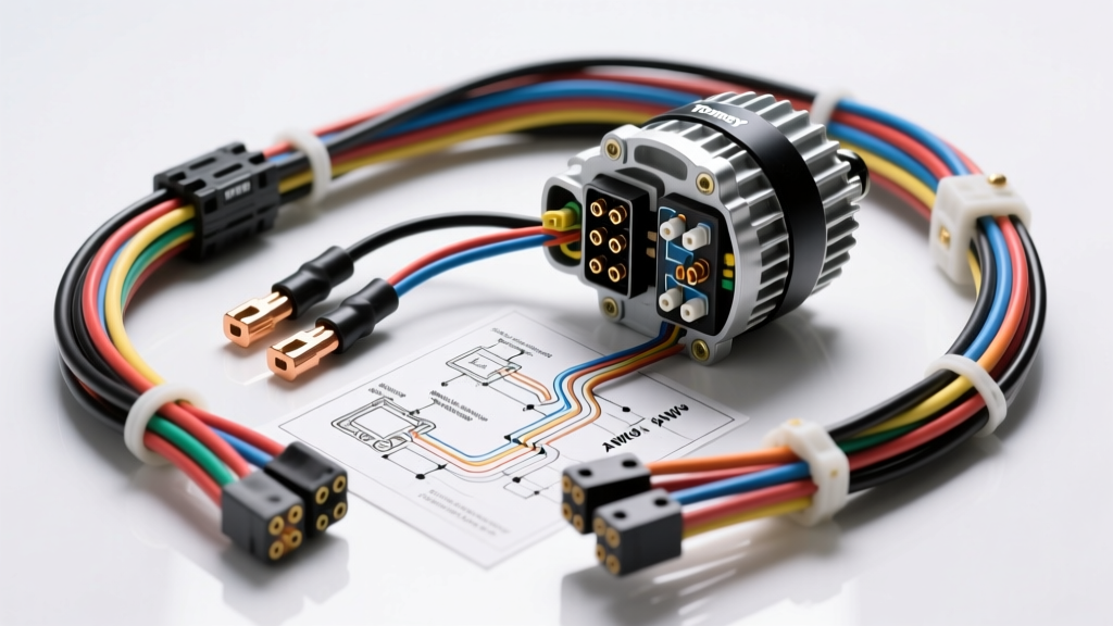
Introduction to the Toomey Auto Electric High-Output Upgrade
Upgrading the charging system in a classic muscle car, hot rod, or heavily accessorized off-road vehicle requires more than simply bolting on a higher-amperage unit. When sourcing heavy-duty charging components, many professional restorers and custom builders turn to Toomey Auto Electric for their robust, high-output alternators and matched wiring harness kits. A factory 63-amp Delco 10SI alternator is entirely inadequate for modern electric cooling fans, EFI fuel pumps, and high-wattage lighting arrays. The Toomey Auto Electric 140A+ CS130D and 12SI hybrid replacements solve this output deficit, but they demand a complete revision of the vehicle's charge and sense circuits.
This practical installation guide details the exact wiring methodology, wire gauge requirements, and Delphi Packard connector specifications necessary to install a Toomey Auto Electric high-output alternator safely. Improper wiring of a 140A+ unit is a primary cause of engine bay fires and melted bulkhead connectors. By following these SAE J1113 compliant wiring practices, you will ensure maximum charging efficiency and long-term electrical reliability.
Required Tools and Electrical Materials
Before beginning the installation, gather the following specialized automotive electrical tools and materials. Do not attempt to crimp high-current circuits with standard pliers.
- Wire: 4 AWG SXL (Cross-linked polyethylene) primary wire for the main charge circuit; 1/0 AWG welding cable for the engine ground; 12 AWG TXL wire for the 3-wire harness.
- Connectors: Delphi Packard 56-series weatherpack male and female terminals, 3/8-inch ID heavy-duty copper ring terminals.
- Tools: Open-barrel automotive wire crimper (specifically for Packard terminals), heavy-duty hydraulic or ratcheting lug crimper for 4 AWG and 1/0 AWG wire, wire strippers.
- Insulation: Adhesive-lined polyolefin heat shrink tubing (3:1 shrink ratio) and corrugated split loom.
- Protection: 150A ANL or Mega Fuse with an inline fuse holder.
Pre-Installation Bench Testing
Never install an alternator without bench-testing it first. To verify the internal voltage regulator and diode trio of your Toomey Auto Electric unit, mount it in a vise using soft jaws. Connect a fully charged 12V battery to the B+ terminal (Case Ground for the negative). Using a jumper wire, momentarily apply 12V to the 'F' (Field/Exciter) terminal. Connect a multimeter to the B+ terminal and the case. Spin the pulley using a high-torque cordless drill and a serpentine belt loop. The output voltage should immediately jump to between 13.8V and 14.4V. If the voltage remains at battery rest (12.6V) or spikes erratically, the unit requires warranty service before installation.
Step-by-Step Wiring Installation
Step 1: Upgrading the Engine Block Ground
High-output alternators push massive current through the engine block to return to the battery. The factory braided ground straps are prone to corrosion and cannot handle 140+ amps without creating a severe voltage drop. Remove the factory ground strap. Cut a length of 1/0 AWG flexible welding cable to reach from the battery negative terminal to a clean, bare-metal mounting point on the engine block or cylinder head. Crimp 3/8-inch copper lugs using a ratcheting crimper, seal them with adhesive-lined heat shrink, and bolt them down. Torque the engine block ground bolt to 25 ft-lbs to ensure a gas-tight mechanical connection.
Step 2: Routing the Main Charge Wire
The most critical failure mode in high-amp upgrades is using undersized charge wires. The factory 10 AWG or 8 AWG wire will overheat and melt under a continuous 100A+ load. You must run a dedicated 4 AWG SXL charge wire from the alternator's B+ post directly to the battery positive terminal.
- Crimp the Alternator End: Use a 3/8-inch ID copper ring terminal on the 4 AWG wire. Slide a piece of adhesive heat shrink over the wire before crimping. Once crimped, heat the tubing until the adhesive oozes from the edges.
- Route the Cable: Route the 4 AWG wire along the inner fender, maintaining at least 3 inches of clearance from exhaust manifolds and headers. Secure it with UV-resistant zip ties every 8 inches.
- Install the Fuse: Cut into the 4 AWG wire within 18 inches of the battery positive terminal. Install a 150A Mega Fuse holder. This protects the vehicle from a dead short in the event the charge wire chafes against the chassis.
- Terminate at Battery: Crimp the final ring terminal and secure it to the battery positive post. Torque the M8 B+ terminal nut on the Toomey alternator to exactly 12 Nm (106 in-lbs). Over-torquing can crack the internal rectifier bridge.
Step 3: Wiring the Toomey Auto Electric 3-Wire Harness
To achieve optimal voltage regulation, especially at idle, the Toomey Auto Electric unit utilizes a true 3-wire configuration. This setup utilizes remote voltage sensing, allowing the regulator to monitor actual battery voltage rather than the voltage at the alternator case, compensating for wiring losses. For deeper insights into remote sensing theory, refer to the technical archives at MAD Enterprises.
Construct the pigtail using 12 AWG TXL wire and Delphi Packard 56-series female terminals. Insert the terminals into the weatherpack connector housing until you hear a distinct click. Apply dielectric grease to the cavity before mating it to the alternator.
Toomey Auto Electric 3-Wire Pinout Reference
| Terminal Pin | Wire Color | Function | Routing Destination |
|---|---|---|---|
| Pin A (Sense) | Orange (12 AWG) | Remote Voltage Sense | Route directly to the battery positive post or the main starter solenoid B+ lug. Must have inline 10A fuse. |
| Pin F (Field) | Pink (12 AWG) | Ignition Exciter | Connect to a 12V ignition-switched source. Use a relay if drawing from a low-current ignition switch circuit. |
| Pin L (Lamp) | Brown (12 AWG) | Dashboard Indicator | Connect to the dashboard 'ALT' or 'GEN' warning light circuit. If no light is used, cap the wire securely. |
| Case / B- | N/A (Ground) | Alternator Ground | Grounds internally through the aluminum mounting brackets to the engine block. |
Final Testing and Voltage Drop Diagnostics
Once all connections are secured, double-checked, and insulated, it is time to test the system. Start the engine and turn on all major electrical loads: headlights (high beam), electric cooling fans, HVAC blower on high, and rear window defroster. This simulates maximum electrical demand.
Performing the Voltage Drop Test
Using a digital multimeter set to DC Volts, perform a voltage drop test across the positive charge circuit. Place the red probe on the alternator B+ post and the black probe on the battery positive post. With the engine at 2000 RPM and loads active, the multimeter should read less than 0.2V. If the reading is higher (e.g., 0.5V or more), you have high resistance in the charge wire, a poor crimp, or an undersized cable. A high voltage drop forces the Toomey Auto Electric regulator to push higher voltages to compensate, leading to premature diode failure.
Next, test the ground side. Place the red probe on the alternator case and the black probe on the battery negative terminal. The reading must be less than 0.1V. If it exceeds this, clean the alternator mounting brackets and verify your 1/0 AWG ground cable.
Ripple Voltage and Diode Health
Switch your multimeter to AC Volts. Place the probes on the battery positive and negative terminals. With the engine running at 1500 RPM, the AC ripple voltage should not exceed 0.1V AC (100mV). Higher ripple indicates a failed diode in the rectifier assembly, often caused by excessive heat from poor engine bay ventilation or a slipping drive belt. Ensure your serpentine belt is tensioned to the manufacturer's specification, typically requiring 130-150 lbs of force on the tensioner.
Troubleshooting Common Installation Errors
- Alternator Whines Through Audio System: This is almost always a ground loop or a failing diode trio. Verify that the audio head unit and amplifiers are grounded to the same clean chassis point as the main battery ground. Check the AC ripple voltage as outlined above.
- Battery Overcharging (15.5V+): The remote sense wire (Pin A / Orange) is likely broken, disconnected, or blown inline fuse. When the sense circuit is open, the regulator defaults to internal case sensing, which can be inaccurate, or it maxes out the field current trying to find the battery.
- Undercharging at Idle (12.2V): The pulley ratio is incorrect. High-output alternators require a specific pulley ratio (usually 2.8:1 to 3.1:1) to reach their cut-in speed at engine idle. If you are using a stock crankshaft pulley, you may need to install a smaller alternator pulley from the Toomey Auto Electric accessory catalog to increase rotor RPM at idle.
- Melted Pigtail Connector: Caused by using stamped brass terminals instead of copper, or failing to use the correct open-barrel crimper for the Packard 56-series terminals. A poor crimp creates resistance, generating intense heat directly at the plastic connector housing.
Conclusion
Installing a Toomey Auto Electric high-output alternator transforms a vehicle's electrical capabilities, supporting modern EFI, massive audio systems, and auxiliary lighting. However, the alternator is only as capable as the wiring that supports it. By strictly adhering to 4 AWG charge wire standards, utilizing remote voltage sensing, and executing flawless Delphi Packard crimps, you guarantee a charging system that is both fire-safe and exceptionally reliable. Always consult the specific wiring schematic provided with your exact Toomey unit, as regulator pinouts can vary slightly between the CS130D and 12SI hybrid platforms.