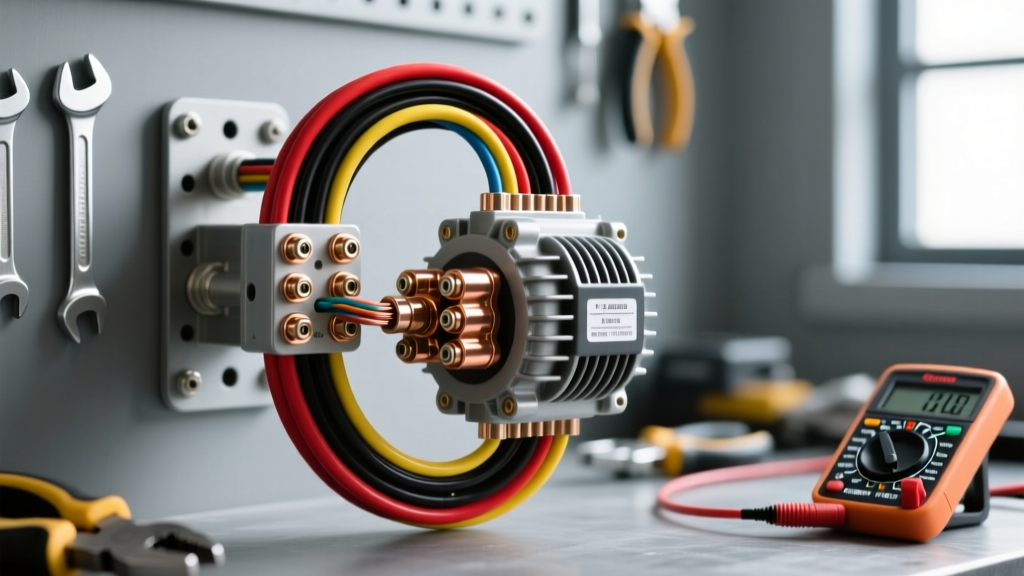
The Upstate Auto Electric Standard for Heavy-Duty Charging
Upstate New York's harsh winters, heavy-duty agricultural demands, and rugged off-road environments birthed a specific breed of auto electrical resilience. When fleet managers, off-grid RV builders, and heavy-equipment enthusiasts refer to the 'Upstate Auto Electric' standard, they are talking about bulletproof, high-amperage charging systems capable of sustaining snowplows, heavy winches, and massive inverter banks without voltage sag. Upgrading from a factory 105-amp alternator to a 220-amp or higher high-output unit requires much more than just bolting on a new case. It demands a complete re-architecture of the vehicle's primary charge and ground circuits.
This practical installation guide details the exact methodology for routing, fusing, and terminating heavy-gauge wiring to ensure your high-output alternator performs to its maximum potential. By following these heavy-duty protocols, you prevent voltage drop, eliminate fire hazards, and ensure your electrical system survives extreme environmental conditions.
Phase 1: Sizing the High-Output Architecture
Alternator and Pulley Ratio Dynamics
High-output alternators (typically 200A to 300A) generate immense thermal and electrical loads. Before unbolting the factory unit, you must verify the pulley ratio and belt configuration. A standard 6-groove serpentine belt is mandatory for anything over 180A; a 5-groove or V-belt will slip, squeal, and glaze under the magnetic drag of a large-stator alternator at idle. Furthermore, ensure your crankshaft pulley (harmonic balancer) is in pristine condition. The torsional vibrations combined with the high rotational resistance of a large-diameter alternator rotor can accelerate rubber dampener failure, leading to catastrophic timing issues on diesel applications.
Phase 2: Wiring Specifications and Component Sourcing
The core of the Upstate Auto Electric methodology relies on minimizing voltage drop between the alternator B+ terminal and the battery positive post. Factory 10 AWG or 8 AWG charge wires will act as resistors when subjected to 200+ amps, choking the alternator's output, triggering internal thermal protection shutdowns, and creating a severe fire hazard. To achieve optimal conductivity, we abandon standard PVC-jacketed copper wire in favor of fine-strand, pure copper welding cable with EPDM or silicone insulation for high-heat resistance.
| Alternator Max Output | Minimum AWG Size (Up to 10 ft) | Minimum AWG Size (10-15 ft) | Recommended Fuse Rating |
|---|---|---|---|
| 140A - 160A | 4 AWG | 2 AWG | 200A ANL / Class T |
| 180A - 220A | 1/0 AWG | 2/0 AWG | 250A ANL / Class T |
| 250A - 300A | 2/0 AWG | 4/0 AWG | 350A Class T |
Phase 3: Termination and Crimping Standards
Never use hammer-style crimpers or solder on 1/0 AWG or larger battery and charge cables. Solder can wick into the fine strands, creating a rigid section that will snap under engine vibration. Instead, use closed-barrel, tinned copper lugs and a 6-ton hydraulic crimper with matched hexagonal dies. This creates a cold-weld connection that is impervious to vibration. Seal the termination with MIL-DTL-22521 spec adhesive-lined heat shrink to prevent moisture ingress and galvanic corrosion, a critical step for vehicles exposed to road salt and humidity.
Phase 4: Step-by-Step Installation Procedure
Step 1: Charge Wire Routing and Fusing
Disconnect the negative battery terminal and isolate it. Remove the factory B+ charge wire. Route the new 1/0 AWG welding cable from the alternator B+ post to a heavy-duty marine-grade busbar mounted near the battery. Do not route this cable near exhaust manifolds, sharp steering shafts, or moving suspension components. Use split-loom tubing and high-temp silicone tape where clearance is tight. Install a 250A Class T fuse within 7 inches of the battery positive terminal. According to ABYC and SAE electrical standards, placing the fuse as close to the power source as possible is non-negotiable to protect the cable in the event of a dead short against the chassis.
Step 2: Exciter and Remote Sense Integration
A high-output alternator requires a clean, ignition-switched 12V signal to 'wake up' the internal voltage regulator. Splice into a known ignition-hot circuit (such as the fuel pump relay trigger or ignition coil feed) using a 14 AWG wire and a 10A inline ATC fuse. More importantly, the remote voltage sense wire (typically 16 AWG or 14 AWG) must be terminated directly at the battery positive post or the main chassis distribution block. If you loop the sense wire back to the alternator's own B+ terminal, the regulator will read the artificially high voltage at the source and undercharge the battery, completely defeating the purpose of the high-amp upgrade.
Step 3: Heavy-Duty Grounding Protocol
A 220A alternator pushing 220A on the positive side requires an equally massive ground path on the negative side. The factory engine-to-chassis ground strap (often a braided 10 AWG wire) will bottleneck the system and cause the alternator to ground through sensitive engine sensors or throttle body cables. Fabricate a new 1/0 AWG ground cable connecting the alternator mounting bracket directly to the vehicle chassis. Add a second 1/0 AWG cable from the engine block to the frame rail. Clean all contact points down to bare, shiny metal using a wire wheel, and coat the terminated lugs with di-electric grease to prevent oxidation.
Phase 5: Validation, Voltage Drop, and Ripple Testing
Once the physical installation is complete, validation is required to ensure the system meets the Upstate Auto Electric standard. Use a digital multimeter to perform a voltage drop test. With the engine running at 2000 RPM and a heavy electrical load applied (headlights on high, cabin fan on max, heated seats active), measure the voltage directly at the alternator B+ post, and then measure at the battery positive post. According to SAE J1141 testing protocols for heavy-duty charging systems, the voltage drop across the charge circuit should not exceed 0.2V (200 millivolts). If your drop is higher, inspect your hydraulic crimps and busbar connections for micro-voids.
Finally, perform an oscilloscope ripple test. Connect the oscilloscope to the battery terminals, set the coupling to AC, and observe the waveform. A healthy high-output alternator should show an AC ripple voltage of less than 50mV. A higher ripple indicates a failed diode in the rectifier assembly, which is common if the alternator was tested on a bench without a battery connected, or if the unit was subjected to voltage spikes during installation. By adhering to these strict wiring, fusing, and testing protocols, your high-output charging system will deliver reliable, uninterrupted power in the most demanding environments.
For further reading on advanced vehicle electrical architecture and harness protection, consult the technical manuals provided by Painless Performance Products regarding high-amperage relay integration and circuit isolation.