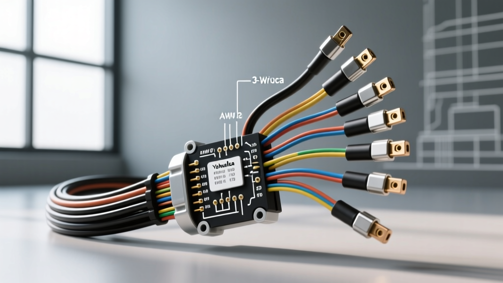
Introduction to Yahualica Auto Electric Architectures
Yahualica auto electric components are widely recognized in the heavy-duty, agricultural, and classic vehicle restoration markets for their robust high-output alternators and solid-state voltage regulators. Whether you are upgrading a classic muscle car to handle modern audio equipment or replacing a failed unit on a heavy-duty work truck, understanding the exact wiring topology of a Yahualica alternator is critical. Unlike generic 1-wire setups that rely on internal sensing and high-RPM self-excitation, a properly wired 3-wire Yahualica system provides superior voltage regulation at idle and extends battery life by monitoring the actual voltage at the main distribution bus.
This complete wiring diagram walkthrough dissects the standard 3-wire externally and internally regulated Yahualica 12V high-output alternator (typically 100A to 140A). We will cover terminal identification, wire gauge (AWG) requirements, routing best practices, and critical modifications required when integrating these units into vehicles with modern LED dashboards.
Yahualica 3-Wire Alternator Pinout & Terminal Identification
Before cutting or crimping any wire, you must correctly identify the alternator case terminals. While Yahualica manufactures various topologies (often mirroring Delco 10SI/12SI or Motorola architectures), the standard 3-wire high-output model utilizes four primary connection points. Below is the master specification chart for terminal identification and wire preparation.
| Terminal ID | Function | Recommended AWG | Standard Wire Color | Connector / Termination |
|---|---|---|---|---|
| B+ (BAT) | Main DC Power Output | 2 AWG or 1/0 AWG | Red | M8 Ring Terminal (Marine Heat Shrink) |
| IG (Ignition) | Regulator Wake / Excitation | 14 AWG | Pink or Red/White | Weatherpack / Metri-Pack 280 |
| F (Field) | Rotor Coil Duty Cycle (External Reg) | 14 AWG | Blue or White | Weatherpack / Metri-Pack 280 |
| S (Sense) | Remote Voltage Feedback | 14 AWG | Orange or Yellow | Inline Fuse Holder to Ring Terminal |
| L (Lamp) | Dash Indicator / Initial Excitation | 16 AWG | Brown or Yellow | Spade Terminal or Harness Plug |
Step-by-Step Wiring Diagram Walkthrough
1. Main Power Output (B+ / BAT) Circuit
The B+ terminal is the main power output of the alternator, directly connected to the internal stator rectifier bridge. For a Yahualica 120A or 140A unit, relying on the factory 10 AWG or 8 AWG charge wire will result in severe voltage drop, excessive heat, and potential fire hazards. According to SAE J1128 standards for low-tension primary cable, you must size the wire based on the maximum continuous amperage and the physical length of the run.
Execution: Use 2 AWG stranded, tinned copper wire. Avoid Copper-Clad Aluminum (CCA) wire, which is commonly sold in big-box auto parts stores; CCA has higher resistance and is prone to galvanic corrosion when crimped to copper terminals. Terminate the alternator end with a 5/16" (M8) closed-end ring terminal, utilizing a dual-wall adhesive-lined heat shrink to prevent moisture ingress. Route the wire to the main starter solenoid battery post or a dedicated high-amperage busbar. You must install a 150A Mega Fuse or ANL fuse within 18 inches of the battery connection point to protect the harness in the event of a short to ground.
2. Ignition and Field Excitation Circuit
The Yahualica voltage regulator requires a 12V reference signal to 'wake up' and begin passing current to the rotor's field coils. In a 3-wire setup, the IG (Ignition) terminal receives this signal. A common failure mode in older vehicles is routing the IG wire directly through the dashboard ignition switch. Over time, the ignition switch contacts degrade, dropping the voltage to the IG terminal below 10.5V. When this happens, the regulator assumes the engine is off and ceases charging.
Execution: Run a 14 AWG wire from a switched 12V source (such as the accessory side of the fuse block) to the coil of a standard 30A automotive relay. Use the relay's switched contacts to send full battery voltage directly from the main busbar to the alternator's IG terminal. This ensures the regulator always sees a solid 12.6V+ wake signal, regardless of ignition switch degradation. If you are using an external Yahualica solid-state regulator, the F (Field) wire must be routed from the regulator's F terminal to the alternator's F terminal using shielded 14 AWG wire to prevent electromagnetic interference (EMI) from the spark plug wires from disrupting the pulse-width modulation (PWM) duty cycle.
3. Voltage Sense and Dash Indicator Circuit
The most critical advantage of a 3-wire Yahualica auto electric system is the remote Sense (S) circuit. Internally regulated 1-wire alternators measure voltage directly at the B+ post. If there is a 0.8V drop across the charge wire and factory harness, the battery only receives 13.6V while the alternator outputs 14.4V, leading to chronic undercharging and sulfation.
Execution: Connect a 14 AWG orange sense wire directly to the S terminal. Route this wire away from the main B+ charge wire to prevent inductive coupling. Connect the opposite end directly to the positive post of the battery or the main positive distribution busbar. Crucial: Install a 5A inline ATC fuse on this sense wire within 6 inches of the busbar connection. If the sense wire ever shorts to ground, the alternator will instantly jump to maximum output (16V+), boiling the battery and destroying the vehicle's ECU. The inline fuse protects against this catastrophic failure mode.
The LED Dashboard Modification: If your vehicle uses an LED charge indicator lamp on the dashboard, the L (Lamp) terminal circuit requires modification. Incandescent 194 bulbs draw roughly 250mA, which provides the necessary initial 'bootstrap' current to magnetize the rotor before the alternator reaches self-excitation RPM. LEDs draw less than 20mA, which is insufficient. You must solder a 10-ohm, 2-watt ceramic resistor in parallel with the LED indicator wire to simulate the electrical load of an incandescent bulb, ensuring reliable low-RPM charging initialization.
Common Wiring Faults & Diagnostic Decision Tree
Even with a flawless diagram, real-world environments introduce variables. Use the following diagnostic table to troubleshoot common Yahualica alternator wiring anomalies.
| Symptom | Probable Cause | Diagnostic & Fix Procedure |
|---|---|---|
| Alternator requires 2500+ RPM to begin charging | Insufficient initial excitation current on the L (Lamp) circuit or missing IG relay. | Verify dash bulb is incandescent or install 10-ohm parallel resistor. Check for voltage drop on IG wire; install a wake relay if drop exceeds 0.5V. |
| Battery voltage reads 13.2V at idle, but 14.4V at alternator B+ post | Sense (S) wire is incorrectly jumpered to the B+ post at the alternator. | Disconnect S wire from B+ post. Reroute 14 AWG sense wire directly to the battery positive terminal or main fuse block busbar. |
| Dash charge light flickers in rhythm with engine RPM | AC ripple voltage exceeding 300mV due to a failing rectifier diode or poor chassis ground. | Perform an AC voltage test at the battery with the multimeter set to VAC. If reading is >0.3V AC, check alternator case-to-engine block ground strap. Clean mounting ears to bare metal. |
| System overcharges to 15.5V+ intermittently | High resistance or intermittent open circuit on the Sense (S) wire. | Check the 5A inline fuse on the sense circuit. Inspect the busbar ring terminal for corrosion. The regulator defaults to maximum output if it loses the sense reference. |
Best Practices for Long-Term Reliability
When working with Yahualica auto electric systems, environmental sealing is just as important as electrical conductivity. The engine bay is subjected to extreme thermal cycling, vibration, and corrosive road salts. Always use dual-wall adhesive heat shrink on all ring terminals. When crimping Weatherpack or Metri-Pack connectors for the IG, F, and S terminals, use a proper ratcheting open-barrel crimper (such as the Delphi/Packard specific tool) rather than generic plier-style crimpers. A poor crimp will wick moisture into the wire insulation via capillary action, leading to green copper oxide buildup deep inside the harness.
For further reading on remote voltage sensing and minimizing voltage drop in high-amperage automotive charging systems, refer to the technical archives at Mad Electrical, which provides excellent baseline data on alternator sense circuit routing. Additionally, verifying your crimp pull-strength and wire gauge against SAE J1128 guidelines ensures your custom harness meets OEM safety standards.
Conclusion
A Yahualica high-output alternator is a premium piece of electrical machinery, but its performance is entirely dependent on the quality of the surrounding wiring harness. By adhering to proper AWG sizing, utilizing remote voltage sensing, and implementing relay-driven excitation circuits, you guarantee that the alternator operates at peak efficiency. Proper execution of this 3-wire diagram will result in a rock-solid 14.2V to 14.4V at the battery terminals under all load conditions, ensuring your vehicle's electrical architecture remains stable and reliable for years to come.