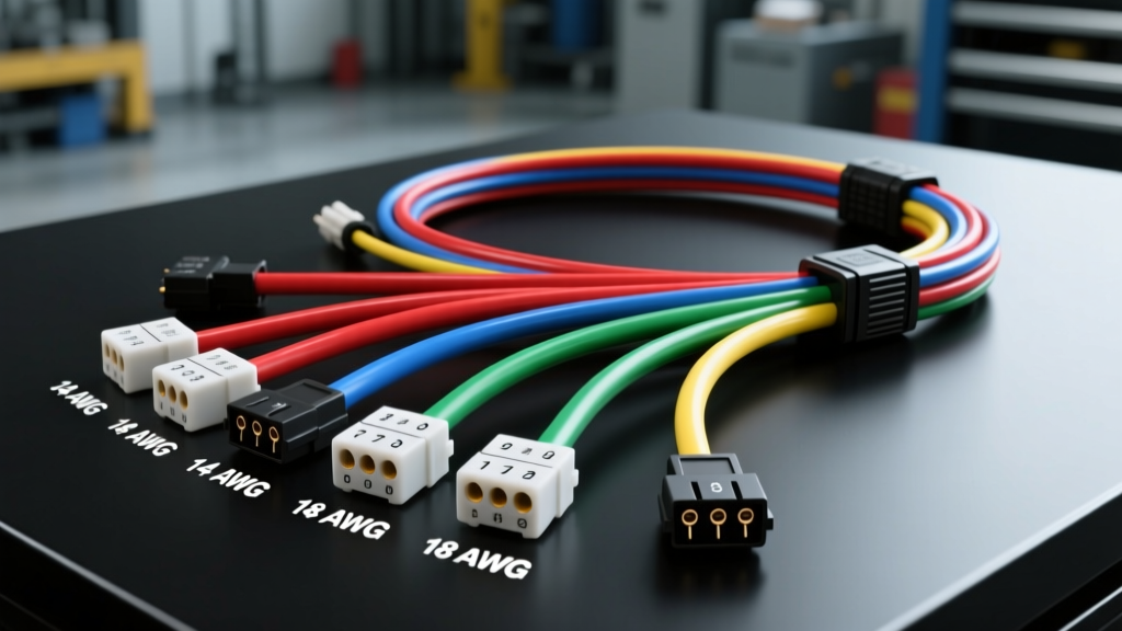
Architecture Overview: Morales Auto Electric Series 400
The Morales Auto Electric Series 400 wiring harness is engineered specifically for high-demand restomod applications, engine swaps (notably GM LS/LT and Ford Coyote platforms), and custom chassis builds. Unlike standard universal kits that rely on PVC-insulated wire, the Series 400 architecture utilizes TXL (Thin-wall cross-linked) and GXL primary automotive wire. This insulation type provides superior resistance to under-hood thermal cycling, abrasion, and chemical exposure, strictly conforming to the SAE J1128 standard for low-tension primary cable.
Termination protocols in the Series 400 mandate the use of Delphi Connection Systems Metri-Pack 280 and Weather-Pack 1200 series terminals. Morales Auto Electric specifies that all crimps must be performed using a TE Connectivity CERTI-CRIMP II tooling system, ensuring a mechanical pull-test retention exceeding 45 lbs and a gas-tight electrical connection that prevents galvanic corrosion over time.
24-Pin Bulkhead Connector Pinout Reference
The firewall transition is managed via a sealed 24-pin bulkhead connector. This module isolates the engine bay's high-heat environment from the climate-controlled cabin. Below is the definitive pinout specification for the Series 400 firewall pass-through, detailing wire gauge, insulation color, and circuit function.
| Pin | Circuit Function | AWG | Wire Color Code | Terminal Type |
|---|---|---|---|---|
| 1 | Headlight Low Beam (Left) | 10 | Yellow w/ Black Tracer | Metri-Pack 280 |
| 2 | Headlight Low Beam (Right) | 10 | Yellow w/ Red Tracer | Metri-Pack 280 |
| 3 | Headlight High Beam (Left) | 10 | Green w/ Black Tracer | Metri-Pack 280 |
| 4 | Headlight High Beam (Right) | 10 | Green w/ Red Tracer | Metri-Pack 280 |
| 5 | Ignition Switched (Run/Start) | 12 | Pink | Metri-Pack 280 |
| 6 | Accessory (Key-On, Off during Crank) | 12 | Brown | Metri-Pack 280 |
| 7 | Starter Solenoid Trigger (S-Terminal) | 14 | Purple | Metri-Pack 280 |
| 8 | Alternator Field Excitation (L-Terminal) | 16 | White w/ Blue Tracer | Metri-Pack 150 |
| 9 | Oil Pressure Sender Signal | 18 | Dark Green | Metri-Pack 150 |
| 10 | Coolant Temperature Sender Signal | 18 | Dark Blue | Metri-Pack 150 |
| 11 | Tachometer Signal (Coil Negative) | 18 | White | Metri-Pack 150 |
| 12 | Electric Fuel Pump Relay Trigger | 14 | Orange | Metri-Pack 280 |
| 13-16 | Reserved for CAN-Bus / ECU Data | 20 | Twisted Pair (Shielded) | Metri-Pack 150 |
| 17-24 | Chassis Ground Distribution | 12 | Black | Metri-Pack 280 |
Note: Pins 13 through 16 utilize a braided copper drain wire shield that must be terminated to a dedicated clean chassis ground within 3 inches of the ECU connector to prevent electromagnetic interference (EMI) from high-voltage ignition coils.
High-Amperage Routing: Starter, Alternator, and EPS
The Series 400 harness separates high-amperage circuits from the primary 24-pin bulkhead to prevent voltage drop and thermal degradation. Morales Auto Electric utilizes MIL-SPEC Tefzel (PTFE) insulated wire for these critical power feeds due to its exceptional dielectric strength and ability to withstand continuous temperatures up to 200°C.
Starter and Alternator Specifications
- Starter Main Feed: 2/0 AWG (00 AWG) fine-strand copper, routed directly from the battery positive distribution block to the starter solenoid B+ stud. Maximum allowable length: 72 inches. Termination requires closed-end copper lugs, crimped with a hydraulic hex-die tool and sealed with dual-wall adhesive heat shrink.
- Alternator Main Output: 4 AWG TXL wire. The Morales kit integrates an inline 150A Mega-Fuse within 18 inches of the alternator B+ terminal to protect against catastrophic short circuits in the event of a front-end collision.
- Alternator Torque Specs: The M8 ring terminal on the alternator output stud must be torqued to exactly 12 Nm (106 in-lbs). Under-torquing leads to micro-arcing and thermal cycling, which rapidly oxidizes the copper strand.
Electric Power Steering (EPS) Integration
Modern restomods frequently utilize rack-mounted EPS systems (such as the Toyota Prius or GM J-body steering columns) which can draw upward of 60 amps under full-lock parking maneuvers. The Series 400 includes a dedicated EPS power module:
- Feed Wire: 4 AWG Red Tefzel, sourced directly from the main battery distribution bus.
- Ground Wire: 4 AWG Black Tefzel, terminated to the vehicle's primary frame rail ground stud, not the engine block or suspension components.
- Control Signal: 18 AWG shielded wire carrying the Vehicle Speed Sensor (VSS) pulse to the EPS controller to scale assist levels dynamically.
Fuse Block Topology and ISO Relay Logic
The central power distribution module (PDM) in the Series 400 utilizes a weather-sealed fuse block accepting standard ATO/ATC blade fuses, alongside a bank of Bosch-style ISO micro relays. Understanding the internal topology of these relays is critical for diagnosing parasitic draws or failed actuations.
| Relay Pin | Function | Series 400 Wire Color | Source / Destination |
|---|---|---|---|
| 30 | Common (Power In) | 10 AWG Red | Fused 12V+ Battery Bus |
| 87 | Normally Open (Load Out) | 10 AWG Circuit Specific | Fan Motor / Fuel Pump / A/C Clutch |
| 86 | Coil Power | 14 AWG Pink | Ignition Switched 12V+ |
| 85 | Coil Ground (Trigger) | 16 AWG Circuit Specific | ECU Ground Driver / Thermal Switch |
| 87a | Normally Closed (Unused) | N/A | Sealed with silicone plug |
Morales Auto Electric integrates internal flyback diodes within the relay sockets for Pins 85 and 86. This suppresses the inductive voltage spike (which can exceed 100V) generated when the ECU drops the ground trigger, protecting sensitive solid-state ECU driver transistors from catastrophic failure.
Sensor Signal Shielding and EMI Mitigation
With the proliferation of high-output ignition systems (such as CDI and coil-near-plug setups), electromagnetic interference (EMI) is a primary cause of erratic idle and false knock sensor readings. The Morales Auto Electric Series 400 addresses this through strict twisting and shielding protocols.
For the Crankshaft Position Sensor (CKP) and Camshaft Position Sensor (CMP), the harness utilizes a 20 AWG twisted-pair configuration. The wires are twisted at a rate of 12 turns per foot. This common-mode noise rejection ensures that any EMI induced into the harness affects both the signal and return wires equally, allowing the ECU's differential amplifier to cancel out the interference. The braided shield surrounding these pairs is grounded exclusively at the ECU end (Pin 18 on the Morales ECU breakout), preventing ground loops that would otherwise turn the shield into an antenna.
Diagnostics: Voltage Drop and Termination Testing
When troubleshooting a Morales Auto Electric Series 400 installation, resistance testing with a multimeter is insufficient for identifying high-current faults. A wire with a single intact copper strand will show 0.1 ohms of resistance but will fail catastrophically under a 50-amp load. Instead, technicians must perform dynamic voltage drop testing.
Voltage Drop Testing Protocol
- Preparation: Set the digital multimeter (DMM) to the DC Volts scale (20V range). Ensure the vehicle battery is fully charged (minimum 12.6V resting).
- Positive Side Testing: Place the DMM's red probe directly on the battery positive post (not the clamp). Place the black probe on the alternator B+ terminal or starter solenoid B+ stud.
- Load Application: Start the engine and engage the electrical load (e.g., command the cooling fans and headlights ON).
- Evaluation: The DMM should read less than 0.2V. A reading of 0.5V or higher indicates excessive resistance at the Morales inline Mega-Fuse holder, the distribution block lug, or the bulkhead connector. According to Motor.com diagnostic standards, any single connection point in a high-amperage circuit should not exhibit a voltage drop greater than 0.1V.
- Ground Side Testing: Move the red probe to the alternator casing or starter casing, and the black probe to the battery negative post. Under load, the ground-side voltage drop must also remain below 0.2V. If the drop is high, inspect the 4 AWG ground strap and the M10 chassis bolt for powder-coating insulation or rust.
By adhering strictly to these Morales Auto Electric specifications, builders ensure a robust, fault-tolerant electrical architecture capable of supporting modern fuel injection, high-output charging systems, and electric steering accessories without thermal degradation or signal corruption.