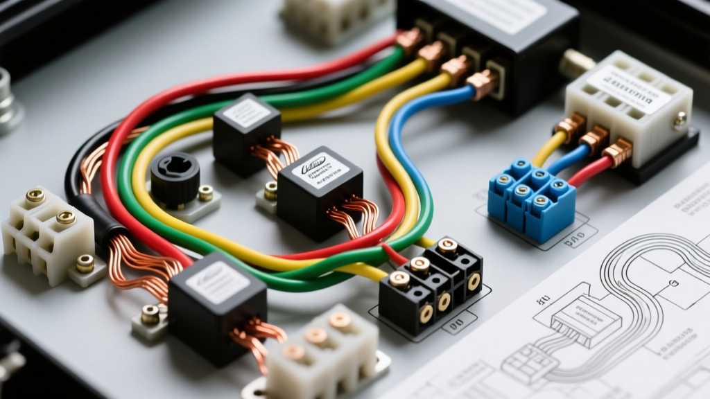
The Lucas Legacy: Decoding the Spitfire Schematic
Classic British sports cars are celebrated for their nimble handling and vintage charm, but their electrical systems are often viewed with unwarranted trepidation. Performing high-quality spitfire auto electric services requires discarding modern automotive assumptions and fully embracing the logic of British Standard wiring diagrams. The Triumph Spitfire, particularly the 1500 models produced between 1975 and 1980, utilizes a Lucas-generated electrical architecture that is remarkably logical once you understand its foundational rules.
Unlike modern vehicles that rely on multiplexed CAN-bus networks and thin-gauge signal wires, the Spitfire operates on a robust, hardwired 12-volt DC system. Every wire has a specific color-coded identity, and every circuit is mapped directly from the battery to the component. This complete wiring diagram walkthrough will decode the Lucas schematic, provide modern AWG equivalents for restoration, and outline critical upgrades to ensure your classic Triumph remains reliable on modern roads.
British Standard Wire Color Codes & AWG Equivalents
The cornerstone of any spitfire auto electric service is understanding the British Standard wire color coding system. Lucas utilized a base-color and tracer-color system. The base color indicates the general circuit function, while the tracer (the stripe) identifies the specific component or branch within that circuit. For example, a Green wire with a White tracer (Green/White) belongs to the fused ignition circuit (Green) and routes to a specific accessory (White).
When sourcing replacement wire or performing a full harness rebuild, it is crucial to match the original cross-sectional area to prevent voltage drop and overheating. Below is a translation of standard Lucas metric sizing to modern SAE J1128 Low Tension Primary Cable AWG standards.
| Lucas Base Color | Circuit Function | Lucas Area (mm²) | SAE AWG Equivalent | Common Tracer Examples |
|---|---|---|---|---|
| Brown (N) | Unfused Battery Live (Constant 12V) | 2.60 - 4.65 | 14 - 10 AWG | N/A (Usually solid brown) |
| White (W) | Ignition Switched (Unfused) | 0.65 - 1.30 | 18 - 16 AWG | White/Red (Tachometer) |
| Green (G) | Fused Ignition Supply | 0.65 - 1.30 | 18 - 16 AWG | Green/Brown (Alternator Field) |
| Blue (U) | Headlights & High Beams | 1.30 | 16 AWG | Blue/White (High Beam) |
| Red (R) | Tail Lights & Side Markers | 0.65 | 18 AWG | Red/Green (Right Side Tail) |
| Black (B) | Earth / Ground | 0.65 - 2.60 | 18 - 14 AWG | N/A (Usually solid black) |
For an authoritative reference on original harness specifications, technicians should consult the Auto Sparks Lucas Wiring Colour Codes Guide, which remains the gold standard for British classic car restorations.
Walkthrough 1: Alternator and Charge Circuit (Lucas 18ACR)
The later Spitfire 1500 models were equipped with the Lucas 18ACR alternator, which features an internal voltage regulator. This was a massive improvement over the earlier external 4TR relay setups, but it still requires precise wiring to function correctly. When performing spitfire auto electric services on the charging system, you will be dealing with three primary terminals on the back of the alternator.
Pin Configuration and Wiring Paths
- B+ Terminal (Output): This is the main power output. The diagram calls for a heavy Brown wire. In modern AWG terms, this must be 10 AWG (or 5.0mm²) to handle the 45-amp output without resistance. This wire routes directly to the starter solenoid battery post or the main junction block.
- IND Terminal (Indicator): This terminal connects to the ignition warning light on the dashboard. The wire color is Brown/Yellow (16 AWG). It provides the initial excitation current to the alternator rotor. If this bulb burns out, the alternator will not 'excite' and will fail to charge upon startup.
- FLD Terminal (Field): Connected via a Green/Brown wire (16 AWG), this circuit routes back to the internal regulator to monitor and control the magnetic field strength based on system voltage demands.
Diagnostic Tip: If the alternator is not charging, bypass the harness by running a temporary 14 AWG jumper from the B+ terminal to the IND terminal. If the alternator begins charging, the fault lies in the dashboard warning light bulb or the Brown/Yellow harness wire, not the alternator itself.
Walkthrough 2: Ignition, Starter, and Ballast Bypass
The Spitfire utilizes a ballast resistor wire hidden within the main harness to reduce voltage to the ignition coil during normal running, thereby extending the life of the points and condenser. However, during cranking, the coil needs a full 12 volts to generate a strong spark.
Tracing the diagram from the starter solenoid, you will find a White/Yellow wire (14 AWG). This is the ballast bypass circuit. When the key is turned to the 'Start' position, the solenoid engages and simultaneously sends full battery voltage down the White/Yellow wire directly to the positive terminal of the ignition coil. A common failure point during spitfire auto electric services is a corroded spade connector on this specific bypass wire, resulting in a weak spark and a no-start condition exclusively while cranking.
Walkthrough 3: Earth Points and the 'Prince of Darkness' Myth
The notorious reliability issues associated with Lucas electrics are rarely due to poor engineering; they are almost entirely the result of poor grounding (earth) practices over decades of use. The Spitfire does not run dedicated ground wires back to the battery for every component. Instead, it relies on the steel chassis and body panels to complete the circuit.
When reading the wiring diagram, any component showing a Black wire terminating in a ring terminal is a chassis ground. The most critical ground points to service include:
- Engine to Chassis Strap: A braided copper strap located near the engine mount. If this corrodes, the starter motor will attempt to ground through the throttle cable or heater hoses, causing them to melt.
- Steering Column Ground: The horn and headlight dimmer switch rely on the steering column's physical connection to the chassis. A missing nylon isolator bushing or corroded column clamp will cause the horn to sound continuously or fail entirely.
- Tail Light Housings: The rear lamp assemblies ground through their mounting screws into the steel rear valance. Rust between the housing and the body panel causes 'sympathetic lighting,' where applying the brakes causes the turn signals to dimly illuminate.
Critical Service Upgrade: Headlight Relay Conversion
One of the most vital upgrades you can perform during spitfire auto electric services is the installation of a headlight relay kit. From the factory, the full amperage draw of the halogen headlamps (approx. 10 amps combined) is routed from the battery, through the bulkhead, up into the steering column, through the Lucas 35756 multi-switch, and back out to the headlights. This long run of 16 AWG Blue wire results in severe voltage drop, yielding dim headlights and overheating the fragile steering column switch.
Relay Installation Schematic
To resolve this, install two standard Bosch-style 30A SPDT relays (one for low beam, one for high beam) in the engine bay near the voltage regulator.
- Pin 30 (Power In): Connect to the battery positive via an inline 20A fuse using 12 AWG Red wire.
- Pin 87 (Power Out): Connect directly to the headlight Blue (low) or Blue/White (high) wires using 12 AWG wire.
- Pin 85 (Ground): Secure to a clean chassis ground using 14 AWG Black wire.
- Pin 86 (Trigger): Tap into the original headlight feed wires at the bulkhead connector. The factory switch now only carries the milliamp load required to trigger the relay coil, preserving the Lucas switch and delivering full 14.2V directly to the lamps.
For comprehensive factory schematics and torque specifications for electrical components, always keep a copy of the Haynes Triumph Spitfire Repair Manuals in your workshop. Mastering these diagrams transforms the Spitfire from a frustrating puzzle into a highly reliable, beautifully simple classic sports car.