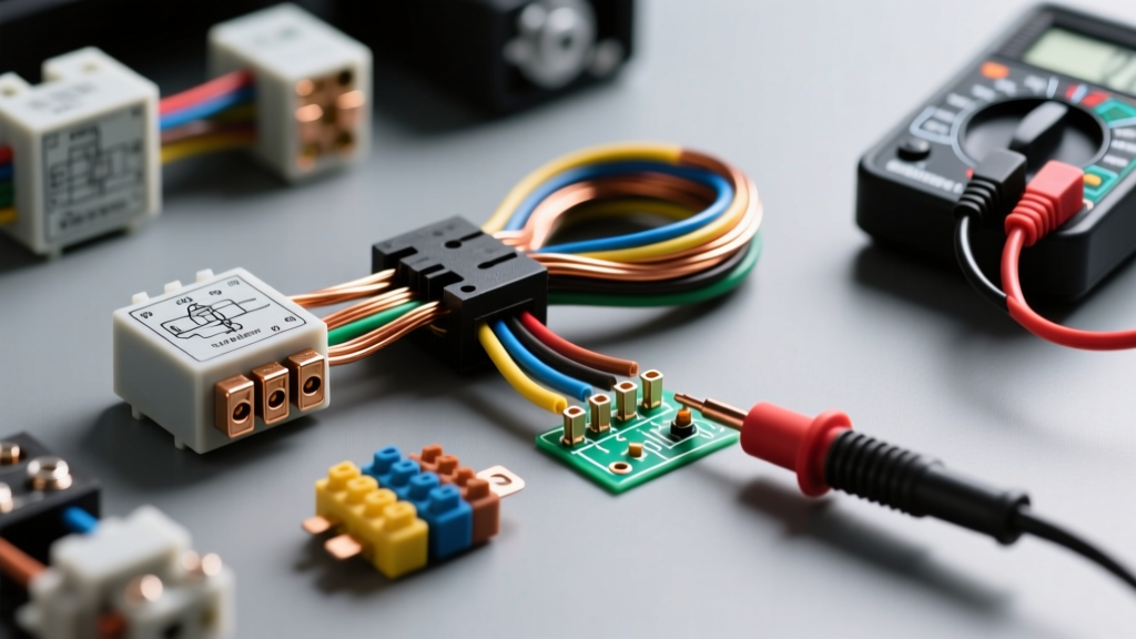
The Core Philosophy of Auto Electric Troubleshooting
When approaching vehicle electrical systems, many beginners feel overwhelmed by the sheer volume of wires, connectors, and control modules hidden behind the dash and buried in the engine bay. The Doug Lenz auto electric methodology strips away this intimidation by focusing on practical, no-nonsense fundamentals. Instead of memorizing thousands of vehicle-specific wiring diagrams, this approach teaches you to understand the universal physics of the 12-volt automotive circuit. Whether you are diagnosing a no-crank condition on a 2015 Silverado or tracing a parasitic draw on a Honda Civic, the foundational rules of voltage, current, and resistance remain exactly the same.
In this comprehensive guide, we will break down the essential building blocks of automotive electrical diagnostics. By mastering wire sizing standards, relay logic, and the critical voltage drop test, you will transition from simply swapping parts to accurately diagnosing the root cause of electrical faults.
Understanding the 'Big Three' in a 12V Automotive System
Every automotive electrical fault can be traced back to an anomaly in one of three electrical properties: Voltage (the pressure), Current (the flow), or Resistance (the restriction). A common mistake beginners make is measuring a circuit with the power disconnected, which only reveals resistance and continuity, completely ignoring how the circuit behaves under a real-world load.
- Voltage (Volts - V): The electrical pressure provided by the battery or alternator. A fully charged resting battery should read 12.6V. A running charging system should read between 13.7V and 14.7V.
- Current (Amperage - A): The actual volume of electrons flowing through the wire. A starter motor might draw 150A to 250A under load, while an LED interior dome light draws less than 0.5A.
- Resistance (Ohms - Ω): The opposition to current flow. In automotive wiring, we want near-zero resistance in our power and ground cables, and specific, engineered resistance in components like fuel injectors or heating elements.
According to the ASE A6 Electrical/Electronic Systems certification standards, understanding Ohm's Law (V = I x R) is mandatory. If resistance in a corroded connector increases, current flow drops, and the component (like a headlight or fuel pump) will underperform, even if the battery voltage is perfect.
Automotive Wire Sizing and Insulation Standards
Using the correct wire gauge is critical to prevent voltage drop, melted insulation, and electrical fires. Automotive wire is not the same as standard household copper wire. It is stranded for flexibility and features specialized insulation designed to withstand under-hood temperatures, oil, and battery acid.
The SAE J1128 standard defines the requirements for automotive primary wire. The most common types you will encounter are GXL (General purpose, thin-wall insulation, rated to 125°C) and TXL (Extra thin-wall, rated to 125°C). Because the insulation is thinner, GXL and TXL wires have a smaller outer diameter than older SXL (Standard wall) wires, allowing more wires to fit into modern, compact connector housings.
Standard AWG Sizing and Amperage Limits for Chassis Wiring
| AWG Size | Max Amperage (Chassis) | Common Automotive Application | Typical Connector Terminal |
|---|---|---|---|
| 18 AWG | 10 Amps | Sensor signals, PCM triggers, interior lighting | Metri-Pack 150, Weather-Pack |
| 14 AWG | 15 Amps | Headlight feeds, fuel pump power, horn circuits | Weather-Pack, Deutsch DT |
| 12 AWG | 20 Amps | Power windows, seat heaters, blower motor (low) | Metri-Pack 280 |
| 10 AWG | 30 Amps | ABS module power, cooling fan relays, ABS pumps | Metri-Pack 630, Maxi-Fuse |
| 8 AWG | 40-50 Amps | Alternator main charge wire, high-amp accessory feeds | Ring terminal, Mega-Fuse |
| 4 AWG | 100-120 Amps | Starter motor positive cable, main battery ground | Heavy-duty ring terminal |
Note: Amperage limits assume single wires in free air at ambient under-hood temperatures. Bundling multiple wires in a loom reduces their heat dissipation and requires derating the maximum amperage.
Demystifying the Standard ISO Automotive Relay
Relays are the workhorses of the automotive electrical system. They allow a low-current switch (like your turn signal stalk or headlight switch) to control a high-current load (like the headlights or fuel pump) without sending heavy amperage through the delicate dashboard wiring.
The most common relay found in modern fuse boxes is the ISO micro relay, which adheres to the DIN 72552 terminal numbering standard. Understanding these five pins is the key to mastering auto electric fundamentals.
- Pin 30 (Common): The main power input from the battery (usually via a fuse). Typically a heavy-gauge red or pink wire.
- Pin 87 (Normally Open - NO): The output to the load (e.g., the fuel pump). Power flows from 30 to 87 only when the relay is energized.
- Pin 87a (Normally Closed - NC): Outputs power when the relay is not energized. Often unused in standard circuits but utilized in alarm or daytime running light (DRL) logic.
- Pin 86 (Coil Power): Receives 12V from the control switch or PCM driver.
- Pin 85 (Coil Ground): Provides the ground path to complete the electromagnetic coil circuit. Many modern vehicles use the PCM to control the ground side of the relay (low-side driver).
Diagnostic Tip: If a relay clicks but the component doesn't turn on, the control circuit (Pins 85 and 86) is working perfectly. The fault lies in the load circuit (Pins 30 and 87). Use a test light on Pin 30 to verify power is reaching the relay box before condemning the wiring to the component.
The Voltage Drop Test: The Ultimate Diagnostic Tool
The cornerstone of the Doug Lenz auto electric approach is the voltage drop test. Beginners often use an ohmmeter to check a wire for continuity. However, a single strand of 18 AWG copper wire hidden inside a corroded 4 AWG battery cable will show 0.0 ohms of resistance on a multimeter, tricking you into thinking the cable is perfect. But when the starter tries to pull 200 amps through that single strand, the voltage will crash.
A voltage drop test measures the circuit while it is under load, revealing hidden resistance that continuity tests completely miss.
Step-by-Step Starter Positive Cable Voltage Drop Test
- Preparation: Disable the ignition or fuel system so the engine will crank but not start. This ensures the starter remains under a continuous heavy load during the test.
- Multimeter Setup: Set your digital multimeter (DMM) to DC Volts (auto-ranging). Do not use the millivolt setting, as the initial surge can overload the meter.
- Probe Placement: Place the red probe directly on the battery's positive post (not the clamp, the actual lead post). Place the black probe directly on the starter motor's main power stud.
- Execute the Test: Have an assistant crank the engine. Read the voltage displayed on the DMM.
- Interpret the Results: A healthy, clean, and properly sized positive starter cable should drop no more than 0.5 volts total during cranking. If your meter reads 0.8V or higher, you have excessive resistance. This could be caused by a loose battery clamp, internal cable corrosion, or a poor connection at the starter solenoid.
For the ground side of the circuit, the acceptable voltage drop is even stricter. According to AutoShop101 Electrical Fundamentals, the maximum allowable voltage drop across any single ground connection (such as the battery negative post to the engine block) is 0.10 volts. If you measure 0.25V across a ground strap during engine cranking, that ground strap is corroded or undersized, and the starter is being starved of the current it needs to spin the flywheel.
Grounding Architecture and G-Points
In automotive wiring, the vehicle's steel chassis and engine block serve as the return path to the battery's negative terminal. Manufacturers map out specific ground locations, usually designated with a 'G' followed by a number (e.g., G101 for an engine bay ground, G200 for an interior cabin ground).
When repairing or adding aftermarket accessories, never assume any bolt on the chassis is a valid ground. Many body panels are painted or powder-coated, which acts as an insulator. Always use a dedicated ground stud equipped with a star washer to bite through the paint, or sand the mounting surface down to bare, shiny metal before securing your ring terminal. After tightening the ground bolt to the manufacturer's specified torque, always apply a dab of dielectric grease or a dedicated battery terminal protector over the connection to prevent galvanic corrosion and moisture intrusion.
Conclusion: Building Diagnostic Confidence
Mastering automotive electrical systems does not require an engineering degree; it requires a disciplined, logical approach to the flow of electricity. By respecting wire gauge limits, understanding the internal logic of ISO relays, and relying on voltage drop testing rather than misleading continuity checks, you can diagnose virtually any 12-volt fault. Keep your multimeter handy, reference the proper wiring diagrams, and always test the circuit under a real-world load.