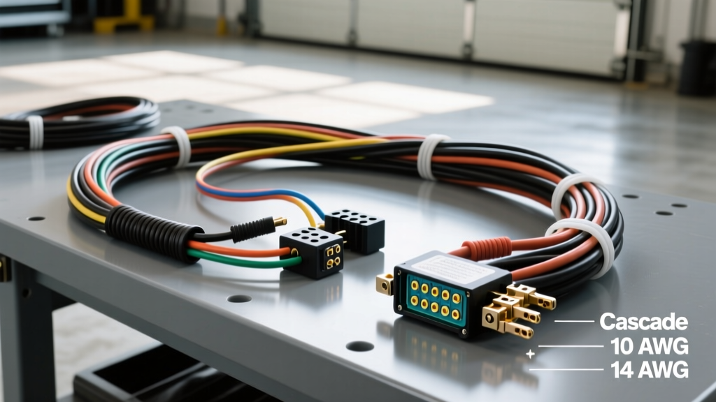
Upgrading Heavy-Duty Lighting with Cascades Auto Electrical Systems
When outfitting commercial trucks, heavy-duty pickups, or off-road rigs with high-draw auxiliary lighting, relying on factory headlight circuits is a recipe for melted switches and voltage starvation. Factory headlight wiring is typically 16 AWG or 18 AWG, designed to handle a maximum of 10 to 15 amps. Modern LED light bars and off-road spotlights frequently pull 20 to 40 amps. To safely manage this electrical load, installing a dedicated cascades auto electrical 40A heavy-duty relay harness is mandatory. This guide provides a comprehensive, step-by-step installation procedure, complete with pinout specifications, crimping standards, and voltage drop troubleshooting.
Why Factory Wiring Fails with High-Draw Accessories
Automotive manufacturers design factory wiring harnesses to meet exact OEM specifications with minimal copper weight to save costs and improve fuel economy. According to SAE J1128 standards for low-tension primary cable, an 18 AWG wire can only safely carry about 7 to 10 amps over short distances before experiencing significant voltage drop and heat generation. If you splice a 30-amp LED light bar directly into a factory high-beam trigger wire, the excessive current will overheat the factory switch, melt the connector housings, and potentially cause an electrical fire. A properly fused relay harness bypasses the factory wiring entirely for the heavy current load, using the factory circuit only as a low-amperage trigger signal.
Cascades 40A Relay Pinout and Wiring Specifications
The cascades auto electrical 40A harness utilizes a standard Bosch-style 5-pin relay (using only 4 pins for SPST single-pole, single-throw operation). Understanding the DIN 72552 relay pin numbering system is critical for a safe installation. Below is the exact specification chart for the harness.
| Relay Pin | Function | Cascades Wire Color | AWG Size | Terminal / Connector Type |
|---|---|---|---|---|
| 30 | Constant 12V+ (Battery) | Red | 10 AWG | Ring Terminal (5/16') with AGU Fuse |
| 87 | Switched Load (To Lights) | Blue | 10 AWG | Deutsch DT Plug (2-Pin) |
| 85 | Chassis Ground | Black | 10 AWG | Ring Terminal (5/16') |
| 86 | 12V Trigger Signal | Yellow | 16 AWG | Posi-Tap / Micro-Tap |
Required Tools and Materials
Do not attempt this installation with household wire strippers or pliers. Proper automotive crimping requires specialized tools to ensure a gas-tight connection that will survive engine bay vibrations and thermal cycling.
- Wire Strippers: Precision gauged for 10 AWG and 16 AWG.
- Crimpers: Ratcheting terminal crimper for 10 AWG non-insulated ring terminals and insulated barrel connectors.
- Heat Source: Heat gun (not a lighter) for 3:1 adhesive-lined marine heat shrink.
- Fasteners: Zip ties, split loom tubing, and self-tapping sheet metal screws with star washers.
- Testing Equipment: Digital Multimeter (DMM) capable of measuring DC voltage and milliohms.
- Chemicals: Dielectric grease and electrical contact cleaner.
Step-by-Step Installation Procedure
Step 1: Battery Isolation and Routing Strategy
Begin by disconnecting the negative battery terminal to prevent accidental short circuits. Plan your routing path from the battery to the relay mounting location, and finally to the auxiliary lights. The 10 AWG red wire must be routed away from exhaust components (minimum 6 inches clearance) and moving steering linkages. Encase the entire length of the 10 AWG red wire in split loom tubing to protect against abrasion against the firewall or chassis.
Step 2: Ring Terminal Crimping and Battery Connection
Strip exactly 3/8' of insulation from the 10 AWG red wire. Slide a piece of 3:1 adhesive-lined heat shrink onto the wire before crimping. Insert the bare copper into the 10 AWG ring terminal barrel and use a ratcheting crimper to compress the terminal. The crimp should be tight enough that the wire cannot be pulled out by hand. Heat the shrink tubing until the adhesive oozes from the ends, creating a waterproof seal. Connect the ring terminal to the positive battery post. If using a side-post battery or an auxiliary bus bar, torque the fastener to the manufacturer's specification (typically 12 Nm or 106 in-lbs for standard 10mm battery nuts).
Step 3: Relay Mounting and Pin 85 Grounding
Mount the cascades auto electrical relay in a vertical orientation with the pins facing downward. This prevents water from pooling inside the Weather-Pack connector housing. For the Pin 85 ground wire, locate a bare metal point on the chassis or engine block. Sand away any paint, powder coating, or rust to expose bare steel. Use a star washer between the ring terminal and the chassis to bite into the metal, ensuring a zero-resistance ground path. Coat the terminal with dielectric grease after tightening to prevent galvanic corrosion.
Step 4: Splicing the Pin 86 Trigger Circuit
The 16 AWG yellow trigger wire requires a switched 12V source. This can be an upfitter switch, a factory high-beam wire, or an ignition-switched fuse box tap. Avoid using cheap 'T-taps' or 'scotch locks', which are notorious for piercing wire insulation and causing green death (copper oxidation). Instead, use a Posi-Tap connector or carefully strip a 1/4' window in the factory wire insulation, solder the 16 AWG yellow wire to the copper strands, and seal it with adhesive heat shrink. As noted by the experts at MAD Electrical, a clean trigger splice ensures the relay coil receives the full 12V required to pull in the internal contactor.
Step 5: Load Termination with Deutsch Connectors
The 10 AWG blue load wire (Pin 87) should be terminated using a Deutsch DT connector to mate with your auxiliary LED light bar. Deutsch connectors utilize solid copper crimp pins and silicone grommets that provide IP68 waterproof sealing. Insert the crimped pins into the DT housing until you hear the retaining clip snap into place. Apply a thin layer of dielectric grease to the mating face of the connector before plugging it into the light bar to prevent moisture ingress and fretting corrosion.
Troubleshooting Common Voltage Drop Issues
Even with a high-quality cascades auto electrical harness, poor installation techniques can lead to voltage drop, resulting in dim lights or relay chatter. Use your digital multimeter to perform a voltage drop test across the circuit while the lights are illuminated.
| Symptom | Probable Cause | Diagnostic Fix |
|---|---|---|
| Lights are dim; relay gets hot | High resistance on Pin 85 Ground | Measure voltage drop from Pin 85 casing to battery negative. Must be under 0.1V. Re-sand chassis ground. |
| Relay clicks rapidly (chatter) | Voltage drop on Pin 86 Trigger | Measure voltage at Pin 86 while cranking/running. If below 10.5V, upgrade trigger wire or change power source. |
| Lights flicker over bumps | Loose crimp on Pin 87 Load | Perform a physical pull-test on the Deutsch DT pins. Re-crimp using proper ratcheting tool. |
| AGU Fuse blows instantly | Short to ground on Red Wire | Inspect split loom routing. Check for pinched wires against firewall or sharp chassis edges. |
Understanding Adhesive Heat Shrink vs. Standard Tubing
One of the most common failure modes in aftermarket automotive wiring is the use of standard PVC heat shrink tubing. Standard tubing does not seal against the wire insulation, allowing capillary action to draw moisture directly into the copper strands. Always use 3:1 shrink ratio tubing with an inner layer of thermoplastic adhesive. When heated to 120°C (250°F), the adhesive melts and flows around the copper strands, creating a hermetic seal that completely blocks oxygen and moisture, preventing the dreaded 'green corrosion' that increases resistance over time.
Final Inspection and Testing
Before reconnecting the negative battery terminal, visually inspect every connection. Ensure the AGU fuse (typically 30A for a 40A relay to account for startup inrush current) is seated tightly in the inline holder. Reconnect the battery and activate the trigger switch. The relay should engage with a distinct, sharp click. Measure the voltage at the Deutsch DT connector pins; it should read within 0.2V of the resting battery voltage (typically 12.4V to 12.6V). If the voltage is lower, re-check your crimps and ground points. By following these exact specifications and utilizing the robust components of a cascades auto electrical system, your auxiliary lighting will operate reliably in the harshest environmental conditions without risking your vehicle's factory electrical architecture.