The Shift to Smart-Node Restomod Wiring
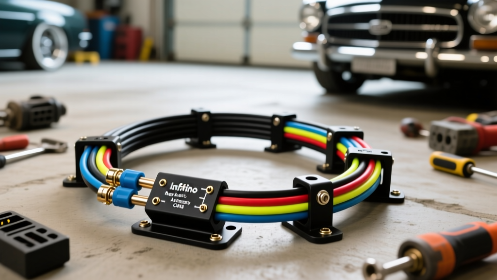
Classic car restomods and EV-swap projects demand far more than a traditional 12-circuit glass-tube fuse box. When integrating modern, high-draw accessories like electric power steering (EPS), brushless PWM cooling fans, and electric AC compressors, voltage drop and Electromagnetic Interference (EMI) become critical failure points. The Infantino Auto Electric modular CAN-bus and high-current auxiliary harness represents a paradigm shift for upgrade and modification projects. By replacing bulky, point-to-point relay nests with a centralized smart-node power distribution system, builders can achieve OEM-level reliability, advanced diagnostic capabilities, and significant weight reduction in the engine bay.
This comprehensive guide details the installation, wiring topology, and diagnostic procedures for integrating the Infantino Auto Electric auxiliary control module into a classic muscle car or custom truck chassis. We will focus on high-amperage routing, CAN-bus termination per SAE J1939 standards, and precise pinout configurations for modern accessory integration.
Infantino Auto Electric System Specifications
Before cutting or crimping a single wire, it is vital to understand the current-carrying capacity and terminal interface requirements of the Infantino smart node. According to Delphi's Electrical Terminal Interface Design guidelines, mismatched crimp tools and incorrect wire gauges are the leading causes of high-resistance connections and subsequent thermal failures in aftermarket harnesses.
| Circuit Designation | Wire Gauge (AWG) | Max Continuous Amperage | Connector Type | Primary Application |
|---|---|---|---|---|
| Main Battery Feed | 4 AWG (TXL) | 150A | Deutsch DT / Ring Terminal | Smart Node Primary Power |
| Main Ground Return | 4 AWG (TXL) | 150A | Ring Terminal (Star Ground) | Chassis/Engine Block Return |
| CAN-Bus High/Low | 18 AWG (Shielded) | 1A | Molex MX150 | ECU / Dash Communication |
| EPS Enable / PWM | 14 AWG (TXL) | 20A | Weather-Pack | Electric Power Steering Trigger |
| AC Compressor Clutch | 10 AWG (TXL) | 30A | ISO Mini Relay Socket | Sanden SD7B10 Electric AC |
| Brushless Fan Control | 16 AWG (TXL) | 5A (Signal) | Deutsch DT | PWM Fan Controller Signal |
Phase 1: High-Current Power Distribution and Grounding
Main Feed and Overcurrent Protection
The Infantino Auto Electric smart node requires a dedicated 4 AWG TXL (cross-linked polyethylene) power feed directly from the battery positive terminal. Do not route this through the factory ignition switch or a standard distribution block. Per NFPA 70 (NEC) and SAE J1171 marine/automotive high-current standards, a 150A ANL fuse must be installed within 7 inches of the battery positive post to protect the main feed in the event of a dead short to the chassis.
Use a ratcheting hex-crimp tool for all 4 AWG ring terminals, and seal the crimp barrel with 3M FP-301 2:1 ratio adhesive-lined heat shrink. This prevents moisture ingress and galvanic corrosion, which is especially critical in restomods that see varied weather conditions.
Star-Point Grounding Topology
High-frequency noise generated by brushless cooling fans and electric AC compressor inverters can easily inject EMI into the vehicle's audio system and ECU sensors if the grounding strategy is flawed. The Infantino system mandates a dedicated 4 AWG ground return wire directly to the battery negative terminal, bypassing the chassis entirely for the main node ground. For auxiliary accessories, fabricate a centralized copper busbar (star-ground point) mounted to the inner fender using a 5/16-18 stainless steel bolt. Torque the busbar mounting bolt to 120 in-lbs and coat the connection in dielectric grease to prevent oxidation.
Phase 2: CAN-Bus Integration and Termination
The Infantino Auto Electric module communicates with aftermarket ECUs (such as Holley Terminator X or Megasquirt MS3) and digital dash clusters via a high-speed CAN-bus network. Proper physical layer installation is non-negotiable for network stability.
- Wire Selection: Use 18 AWG unshielded twisted pair (UTP) for short runs under the dash, or shielded twisted pair (STP) if routing near high-voltage ignition coils or alternator stator wires.
- Twist Rate: Maintain a minimum of one twist per inch to ensure common-mode noise rejection.
- Termination Resistors: The CAN-bus requires exactly two 120-ohm termination resistors—one at each physical end of the network backbone. The Infantino smart node features an internal, switchable 120-ohm resistor. Ensure the DIP switch on the node is set to 'ON' only if the node is at the physical end of the daisy-chain; otherwise, leave it 'OFF' to prevent dropping the network impedance to 60 ohms, which will cause communication timeouts.
- Splicing: Never use solder or twist-ties for CAN-bus splices. Use ultrasonic welding or high-quality crimp splices (e.g., Molex MX150 sealed splices) to maintain the precise characteristic impedance of the twisted pair.
Phase 3: Accessory Circuit Mapping and Pinout Configuration
The core of the Infantino Auto Electric upgrade lies in its programmable smart-node pinout. Below is the standard configuration for a restomod integrating Electric Power Steering (EPS) and an electric AC compressor.
| Pin Number | Wire Color | Function | Signal Type / Load |
|---|---|---|---|
| 1 | Green/White | CAN-High | Differential Data (2.5V - 3.5V) |
| 2 | Blue/White | CAN-Low | Differential Data (2.5V - 1.5V) |
| 3 | Violet | EPS Enable Trigger | 12V+ Output (Max 20A) |
| 4 | Yellow | AC Compressor Relay Trigger | Low-Side Ground Switch |
| 5 | White/Red | PWM Fan Control Signal | 1kHz - 20kHz PWM (5V Logic) |
| 6 | Black | Logic Ground | Sensor / ECU Return |
| 7 | Red | Ignition Switched 12V Input | Wake-Up Signal (1A Max) |
| 8 | Orange | Headlight Dimmer Trigger | Ground Trigger for Dash Backlight |
Integrating the Sanden SD7B10 Electric AC Compressor
When upgrading to a Sanden SD7B10 electric AC compressor, the 12V magnetic clutch draws approximately 18A upon initial engagement. Pin 4 on the Infantino node is a low-side driver, meaning it provides a switched ground path, not a 12V positive feed. You must wire Pin 4 to the control coil ground (Terminal 85) of a 30A Bosch-style ISO mini relay. Connect Terminal 86 to a fused 12V ignition source, Terminal 30 to the battery via a 20A inline fuse, and Terminal 87 to the AC compressor clutch positive wire. This prevents the high inductive kickback voltage from the clutch coil from frying the Infantino node's internal solid-state relay.
Electric Power Steering (EPS) PWM Integration
Toyota Prius or Lexus IS300 EPS racks require a simulated vehicle speed signal to adjust steering assist levels. While Pin 3 provides the primary 12V enable trigger to wake the EPS ECU, advanced builders utilize the Infantino Auto Electric CAN-bus data stream to broadcast a simulated Vehicle Speed Sensor (VSS) CAN ID (typically 0x0B4 or 0x1D0 depending on the specific EPS ECU firmware). This allows the steering rack to dynamically stiffen at highway speeds and provide maximum assist during parking maneuvers, a crucial safety upgrade for heavy restomod front ends.
Diagnostics: Oscilloscope and Voltage Drop Testing
Post-installation validation is where professional builds separate themselves from amateur projects. Relying solely on a multimeter is insufficient for diagnosing high-speed data networks or dynamic voltage drops.
Validating the CAN-Bus Signal
Connect a PicoScope or equivalent automotive oscilloscope to Pins 1 and 2 using breakout probes. With the ignition on and the ECU awake, you should observe a clean, differential square wave. CAN-High should idle at 2.5V and rise to 3.5V during dominant bits. CAN-Low should idle at 2.5V and drop to 1.5V. If the waveform appears jagged, exhibits excessive ringing, or the recessive voltage levels drift, check for missing 120-ohm termination resistors or shield grounding issues.
High-Amp Voltage Drop Troubleshooting
With the engine running and the electric cooling fans and AC compressor engaged simultaneously, perform a dynamic voltage drop test across the 4 AWG main power feed. Place your multimeter's red probe on the battery positive post and the black probe on the Infantino node's main power input stud. A reading greater than 0.15V indicates excessive resistance, likely caused by an undersized crimp, a loose ANL fuse holder, or internal wire strand breakage. Perform the same test on the ground side (battery negative post to node ground stud). Correcting these micro-ohm resistances ensures the smart node's internal logic boards receive clean, stable voltage, preventing erratic accessory behavior and premature module failure.
By treating the Infantino Auto Electric harness not just as a bundle of wires, but as a sophisticated, data-driven power distribution network, your upgrade and modification project will achieve the reliability and performance expected of modern OEM vehicles.