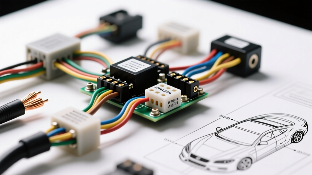
The Philosophy of the Taylor Auto Electrical Upgrade
When enthusiasts and professional engine builders refer to a "Taylor auto electrical" overhaul, they are invoking a standard of high-performance ignition and primary wiring reliability. Upgrading a vehicle's electrical architecture is not merely about swapping old, brittle wires for new ones; it is about optimizing conductivity, eliminating Electromagnetic Interference (EMI), and ensuring that high-output ignition systems receive stable voltage. Whether you are retrofitting a classic muscle car with a modern LS engine or optimizing a dedicated track vehicle, executing a proper Taylor-style electrical upgrade requires strict adherence to wire gauge specifications, terminal crimping protocols, and harness routing geometry.
This comprehensive guide details the exact procedures for upgrading your ignition harness and primary power circuits, utilizing the engineering principles championed by premium manufacturers like Taylor Cable Products. We will cover spiral-core ignition wire selection, primary AWG sizing for high-amperage alternators, and critical EMI mitigation strategies.
Phase 1: High-Performance Ignition Wire Selection & Specs
The foundation of any Taylor auto electrical upgrade begins at the spark plug. Modern electronic fuel injection (EFI) systems, crankshaft position sensors, and wideband O2 sensors are highly susceptible to Radio Frequency Interference (RFI). Using outdated carbon-core or solid copper-core ignition wires will induce noise into the ECU, causing erratic fuel trims and misfires. You must select a spiral-core (helical wound) ignition wire, which provides the necessary resistance to suppress RFI while maintaining ultra-low ohms-per-foot for maximum spark energy.
Ignition Wire Specification Chart
| Wire Series Profile | Diameter | Core Architecture | Resistance Rating | Optimal Application |
|---|---|---|---|---|
| Spiro-Pro Equivalent | 8.0mm | Spiral / Helical | 50 Ω/ft | EFI / High-RPM Racing / Coil-Near-Plug |
| ThunderWire Equivalent | 8.2mm | Spiral / Helical | 500 Ω/ft | Street / Strip / Classic V8 / HEI Distributors |
| StreetWire Equivalent | 8.0mm | Carbon Impregnated | 3,000+ Ω/ft | Budget / Stock Replacements / Low-RPM Only |
For performance applications, the 50 Ω/ft spiral core is the gold standard. According to SAE J2031 standards for high-tension ignition cables, the dielectric strength of the 100% silicone jacket must withstand continuous temperatures up to 500°F (260°C) and momentary spikes of 600°F. When upgrading LS-based engines utilizing D585 coil-on-plug (COP) setups, ensure your custom harness uses high-temp fiberglass braided sleeving over the 8.0mm spiral core wires to protect against exhaust manifold radiant heat.
Phase 2: Upgrading Primary Power and Ground Cables
A common failure point in modified vehicles is the bottleneck created by factory primary power cables. If your Taylor auto electrical project includes upgrading to a 140A to 200A high-output alternator, the factory 8 AWG or 6 AWG charge wire will suffer from severe voltage drop, starving the ignition coils and fuel injectors of necessary voltage. Coils require a minimum of 13.5V at the positive terminal to achieve maximum dwell time and spark intensity.
Primary Cable AWG Sizing Guide (12V System)
| Alternator Output | Run Length (Under 4 ft) | Run Length (4 - 7 ft) | Run Length (Over 7 ft) |
|---|---|---|---|
| 60A - 90A | 6 AWG | 4 AWG | 2 AWG |
| 100A - 140A | 4 AWG | 2 AWG | 1/0 AWG |
| 150A - 200A+ | 2 AWG | 1/0 AWG | 2/0 AWG |
For the ground side, never rely solely on the engine block-to-chassis ground strap. Install a dedicated 2 AWG pure copper ground cable directly from the alternator casing or engine block to the vehicle's main battery negative terminal or a dedicated chassis ground bus bar. This ensures the high-current return path has minimal resistance, stabilizing the entire electrical reference ground for the ECU.
Phase 3: Harness Routing and EMI Mitigation
Routing is where a professional Taylor auto electrical build separates itself from an amateur job. Electromagnetic Induction occurs when high-current primary wires run parallel to low-voltage sensor wires or ignition wires, inducing a "ghost" voltage that confuses the ECU.
- The 90-Degree Rule: Whenever a primary power cable (like the alternator charge wire) must cross an ignition wire harness or a sensor signal wire (like a 5V reference or camshaft position sensor), they must cross at exactly a 90-degree angle. This minimizes the surface area of parallel proximity, virtually eliminating inductive coupling.
- Separation Distances: Maintain a minimum clearance of 2.5 inches between 8mm/8.2mm ignition wires and exhaust headers. For EFI injector harnesses and ignition wires, maintain at least a 1-inch separation. If parallel routing is unavoidable, separate the harnesses by at least 4 inches and use braided metal shielding grounded at one end for the sensor wires.
- Spark Plug Boot Seating: When routing wires to the plugs, use a silicone-based dielectric grease (like Taylor's Z-Compound) inside the spark plug boots. This prevents moisture ingress, prevents the boot from bonding to the ceramic insulator, and ensures the terminal seats with a distinct "click."
Phase 4: Professional Crimping & Termination Protocol
When terminating the heavy-gauge primary cables for your upgrade, soldering is strictly prohibited for high-vibration, high-current automotive applications. Solder can wick up the wire strands, creating a rigid point that will eventually work-harden and snap under engine vibration. Instead, use the following protocol based on SAE J1128 and IPC/WHMA-A-620 standards:
- Stripping: Use a precision wire stripper to remove exactly 5/8" of insulation from the 2 AWG or 1/0 AWG cable. Do not nick or cut the outer copper strands, as this reduces the cross-sectional area and creates a localized hot spot.
- Terminal Selection: Use heavy-wall, tinned copper ring terminals rated for the specific AWG. For alternator studs, use a 3/8" or 5/16" ring size depending on the specific alternator model (e.g., Denso vs. Powermaster).
- Crimping: Use a ratcheting hex-crimp tool or a dedicated hydraulic crimper. A ratcheting tool ensures the exact compression force is applied, deforming the terminal barrel into a hexagonal shape that creates a cold-weld, gas-tight connection with the copper strands.
- Sealing: Slide a piece of dual-wall (adhesive-lined) polyolefin heat shrink over the connection. Apply heat evenly until the adhesive purges slightly from the edges, creating a waterproof seal that prevents galvanic corrosion under the hood.
Integrating Modern Coil Connectors (LS / LT Platforms)
If your Taylor auto electrical project involves an LS or LT engine swap, you will be working with D585 or similar Coil-Near-Plug (CNP) harnesses. These utilize 4-pin Metri-Pack or Delphi connectors. The pinout typically follows this configuration:
- Pin A: Low Reference / Ground (Usually Black or Black/White)
- Pin B: Ignition Control Signal / Trigger from ECU (Usually specific color per cylinder bank)
- Pin C: 12V Switched Power from Ignition Relay (Usually Pink)
- Pin D: Diagnostic / Tachometer Output or Unused (Varies by ECU tuning)
When building a custom ignition harness for these coils, use 16 AWG TXL (Cross-linked polyethylene) wire for the 12V power feeds to handle the cumulative amperage draw of multiple coils firing simultaneously, and 18 AWG GXL wire for the low-current trigger signals. Always use a proper Delphi Metri-Pack crimping tool with the correct die cavity to ensure the terminal tangs lock securely into the connector housing.
Troubleshooting Common Post-Upgrade Misfires
Even with premium components, installation errors can cause issues. Use this diagnostic tree if you experience misfires post-upgrade:
- Symptom: Misfire only at high RPM (above 5,500 RPM).
Cause: Voltage drop in the primary ignition feed or insufficient coil dwell time programmed in the ECU.
Fix: Check voltage at the coil positive terminal under load. If below 12.5V, upgrade the ignition relay power feed wire from 14 AWG to 10 AWG. - Symptom: Random misfires on cylinders routed near the exhaust.
Cause: Heat degradation of the ignition wire dielectric jacket causing the spark to arc to the cylinder head.
Fix: Inspect wires for burn marks. Replace with fiberglass-sleeved Taylor-style wires and apply reflective heat barrier tape to the adjacent header tube. - Symptom: ECU throws cam/crank correlation codes or erratic idle.
Cause: RFI interference from spiral-core wires routed too close to the camshaft position sensor harness.
Fix: Reroute the ignition harness to maintain a 2-inch minimum gap from EFI sensor wiring, ensuring all sensor shields are grounded to the ECU sensor ground, not the chassis.
Executing a true Taylor auto electrical upgrade requires patience, precision tooling, and a deep understanding of automotive electrical physics. By selecting the correct spiral-core ignition wires, properly sizing your primary AWG cables, and strictly adhering to EMI routing protocols, you will build an ignition and power delivery system capable of supporting massive horsepower while maintaining OEM-level reliability. For further reading on high-tension cable standards, refer to the Taylor Cable Products Technical Library and relevant SAE documentation.