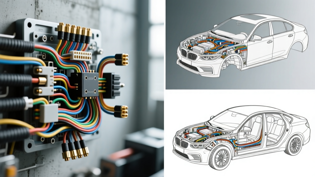
Williams Auto Electrical: Diagnostic Case Studies in Wiring Failures
When analyzing field returns, warranty claims, and diagnostic case studies compiled under the Williams Auto Electrical methodology, a distinct pattern emerges: the vast majority of catastrophic electrical failures are not caused by defective OEM components, but by improper aftermarket installations, poor repair practices, and a fundamental misunderstanding of modern vehicle architecture. Modern vehicles rely on complex multiplexed networks and high-current EV systems where a single wiring error can cascade into module destruction or severe safety hazards.
This guide breaks down the most critical wiring mistakes documented in Williams Auto Electrical diagnostic archives, providing actionable corrections, specific AWG requirements, and vital safety warnings for both 12V and high-voltage systems.
Mistake #1: Ignoring SAE J1128 AWG Standards and Voltage Drop
One of the most frequent errors observed in the field is sizing wire based solely on its ampacity rating while completely ignoring voltage drop over distance. According to SAE J1128 standards for Low Tension Primary Cable, a wire must safely carry the load and maintain sufficient voltage at the destination component.
The Fuel Pump Cavitation Scenario
A common Williams Auto Electrical case study involves the installation of an aftermarket high-flow fuel pump (e.g., Walbro 450 lph) using standard 12 AWG copper wire. While 12 AWG can theoretically handle 20-25 amps in a chassis-wiring scenario, the physical length of the wire from the engine bay relay to the rear-mounted fuel tank creates significant resistance.
- The Error: Using 12 AWG wire over a 14-foot run to a 20A fuel pump.
- The Result: A voltage drop of 1.5V to 2.0V. The pump receives only 11.5V instead of 13.8V, resulting in a 30% drop in fuel flow, fuel rail starvation under boost, and eventual pump burnout due to increased amperage draw as the motor struggles.
- The Fix: Upgrade to 10 AWG or 8 AWG stranded copper wire (never Copper Clad Aluminum / CCA) and utilize a 30A relay with a dedicated 10 AWG power feed directly from the battery positive terminal.
Wire Gauge & Voltage Drop Reference Chart (12V System)
| AWG Size | Max Continuous Amps | Resistance (Ohms/1000ft) | Voltage Drop (10ft run @ 15A) | Common Application |
|---|---|---|---|---|
| 16 AWG | 10A | 4.016 | 0.60V | Interior lighting, horn relay trigger |
| 14 AWG | 15A | 2.525 | 0.38V | O2 sensor heaters, power windows |
| 12 AWG | 20A | 1.588 | 0.24V | Cigarette lighter, auxiliary fans |
| 10 AWG | 30A | 0.998 | 0.15V | High-flow fuel pumps, ABS modules |
| 8 AWG | 45A | 0.628 | 0.09V | Starter solenoid feeds, EV DC-DC |
Mistake #2: CAN Bus Splicing and Termination Disasters
The Controller Area Network (CAN) bus is the central nervous system of modern vehicles. Operating under ISO 11898 standards, the high-speed CAN network relies on differential signaling and precise impedance matching. Williams Auto Electrical diagnostic logs are filled with vehicles exhibiting "U-codes" (network communication faults) caused by improper splicing.
The Scotch-Lok and Untwisted Pair Sin
Technicians frequently tap into the OBD2 DLC (Data Link Connector) pins 6 (CAN-H) and 14 (CAN-L) to install telemetry trackers, aftermarket alarms, or tuning interfaces using insulation-displacement connectors (Scotch-Loks) or T-taps.
- Pin 6 (CAN-H): Typically Orange/Black or Green. Recessive state ~2.5V, Dominant state ~3.5V.
- Pin 14 (CAN-L): Typically Orange/Brown or Green/White. Recessive state ~2.5V, Dominant state ~1.5V.
The Failure Mode: T-taps introduce micro-movements and moisture ingress, leading to galvanic corrosion. This increases circuit resistance. Furthermore, if the aftermarket pigtail is not a tightly twisted pair (minimum 33 twists per meter), it acts as an antenna, injecting electromagnetic interference (EMI) into the network. Finally, adding a module with an internal 120-ohm terminating resistor to an already-terminated network drops the parallel resistance below the required 60 ohms, causing the transceivers to misread dominant and recessive states.
The Williams Protocol Fix: Never use T-taps on data lines. Use military-spec solder sleeves with heat-shrink and dielectric gel. Always measure the CAN bus resistance with a multimeter across Pins 6 and 14 (with the battery disconnected and modules asleep); it must read exactly 60 ohms (± 5 ohms).
Mistake #3: The "Daisy-Chain" Grounding Fallacy
Grounding is the most misunderstood concept in auto electrical diagnostics. A common mistake is "daisy-chaining" multiple high-draw accessories (e.g., HID ballasts, audio amplifiers, or transmission controllers) to a single, shared factory ground stud, such as a G104 or G201 location.
Ground Loops and ECU Noise Injection
When an HID ballast ignites, it pulls up to 15 amps momentarily. If this ballast shares a ground path with an ECU or a sensitive MAF (Mass Air Flow) sensor, the voltage potential on that shared ground wire spikes. Because the ECU reads sensor voltages relative to its own ground, a 0.5V spike on the ground plane translates to a 0.5V error in the MAF signal, causing severe fueling miscalculations.
Actionable Grounding Rules:
- Star Grounding: Run individual ground wires from high-draw components to a dedicated, heavy-gauge distribution block, and then run a single, massive 4 AWG or 2 AWG cable from the block to the chassis or battery negative.
- Hardware Upgrades: Replace factory M6 (6mm) ground studs with M8 or M10 stainless steel studs. Use heavy-duty copper ring terminals with a bell-crimp.
- Surface Prep: Remove all paint, powder coat, and rust down to bare metal. Apply a conductive anti-oxidant paste (not standard dielectric grease, which is an insulator) to the mating surface before torquing the nut to 15-20 Nm.
Critical Safety Warnings: High-Voltage and 48V MHEV Systems
As the industry shifts toward 48V Mild Hybrid Electric Vehicles (MHEV) and full EV architectures, the safety protocols outlined in Williams Auto Electrical training become a matter of life and death. High-voltage (HV) cables are universally shielded and jacketed in bright orange.
Arc Flash and Isolation Protocols
Working on a 48V system can still produce lethal arc flashes if shorted with standard steel tools, while full EV systems (400V to 800V) carry fatal DC current. Adherence to NFPA 70E electrical safety standards is mandatory.
High-Voltage Isolation Decision Tree
- Step 1: Identify. Locate the Manual Service Disconnect (MSD) or the 12V service loop plug specific to the vehicle manufacturer (e.g., Ford's inertia switch loop or Tesla's first responder cut loops).
- Step 2: Disconnect & Secure. Pull the MSD. Lock out and tag out (LOTO) the 12V auxiliary battery negative terminal to prevent contactors from re-engaging.
- Step 3: Wait. HV inverters contain massive capacitors. Wait a minimum of 10 to 15 minutes (consult OEM service manual for exact bleed-down times) before touching any orange cabling.
- Step 4: Verify. Using a CAT III or CAT IV rated digital multimeter (DMM), test the HV terminals phase-to-phase and phase-to-chassis ground. The reading must be strictly 0V.
- Step 5: PPE. Wear Class 0 (1000V) insulated rubber gloves with leather protectors before physically handling HV busbars or motor stator connectors.
Summary of Best Practices
The core philosophy of the Williams Auto Electrical approach is that electrical diagnostics and repairs must be rooted in physics, not guesswork. By respecting AWG voltage drop limitations, preserving the physical geometry of CAN bus twisted pairs, implementing isolated star-grounding topologies, and treating HV systems with rigorous isolation protocols, technicians can eliminate the root causes of 95% of all "ghost" electrical faults and ensure long-term vehicle reliability and operator safety.