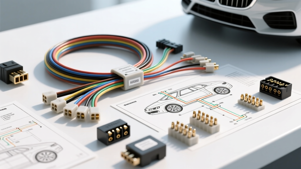
Introduction to Professional Auto Electric Diagnostics
When diagnosing complex electrical faults, professional technicians adhering to the rigorous A&S Auto Electric methodology avoid the common "parts cannon" approach. Throwing alternators or starters at a vehicle without verifying the underlying wiring architecture is a fast track to misdiagnosis, melted harnesses, and stranded customers. Modern vehicle electrical systems rely on precise voltage thresholds, specific wire gauge capacities, and low-resistance ground paths to operate correctly. This guide outlines a comprehensive, step-by-step troubleshooting flow for the two most critical systems in any vehicle: the cranking circuit and the charging system. By following this structured decision tree, you will isolate faults down to the exact pin, connector, or cable before ever unbolting a component.
Phase 1: Establish the Baseline State of Charge (SOC)
Before testing any circuit, the battery must be verified as a stable power source. A surface charge can mask a failing cell, leading to false voltage drop readings during high-amperage draw tests.
- Resting Voltage Test: With the vehicle off and keys out for at least 2 hours, measure the battery terminals. A healthy flooded lead-acid battery should read 12.66V (100% SOC). AGM batteries typically read slightly higher, around 12.80V to 13.00V.
- Load Testing: Apply a carbon pile load equal to half the battery's Cold Cranking Amps (CCA) rating for 15 seconds. According to SAE J1127 standards for battery cable and system performance, voltage should not drop below 9.6V at 70°F (21°C) during this test.
- Terminal Integrity: Inspect the battery posts. Corrosion under the insulation of side-terminal GM batteries or around the clamp of top-post batteries introduces parasitic resistance. Torque battery terminal nuts (typically 8mm or 5/16") to 10-15 Nm to ensure proper clamping force without cracking the lead post.
Phase 2: The Voltage Drop Testing Protocol
The cornerstone of the A&S Auto Electric troubleshooting flow is voltage drop testing. Unlike measuring resistance with an ohmmeter—which uses a tiny internal current that cannot detect high-resistance faults under a real load—voltage drop testing measures the circuit while it is under operational load. As detailed in Fluke's automotive diagnostic guidelines, you place your multimeter in DC Volts, connect the red lead to the power source side of the component/cable, and the black lead to the load side while the circuit is active.
- Acceptable Drop (Power Side): Less than 0.1V per connection, and less than 0.5V total for the entire positive cranking cable run.
- Acceptable Drop (Ground Side): Less than 0.1V per connection, and less than 0.2V total from the starter housing to the battery negative terminal.
- Failing the Test: A reading of 0.8V across a battery cable clamp indicates severe internal corrosion or a loose crimp, starving the starter of amperage and mimicking a bad starter motor.
Phase 3: Cranking Circuit Decision Tree
If the vehicle exhibits a "No Crank" or "Slow Crank" symptom, follow this step-by-step flow to isolate the fault.
Step 1: Verify Starter B+ Supply
Connect your multimeter red probe to the main starter B+ terminal (typically a heavy 4 AWG or 2 AWG cable) and the black probe to the starter housing. Have an assistant crank the engine.
- Result A (Reads > 10.0V): Power supply is good. Proceed to Step 2.
- Result B (Reads < 9.5V): Excessive voltage drop on the positive side. Move the red probe back toward the battery (fuse box, intermediate junction block) until you find where the voltage recovers. The fault lies between the two probe points (e.g., a corroded mega-fuse or degraded 4 AWG cable).
Step 2: Verify Solenoid Engagement Signal (S-Terminal)
Locate the starter solenoid trigger wire. This is usually a 12 AWG or 14 AWG wire terminating in a Delphi Packard Metri-Pack 150 or 280 series connector, or a simple ring terminal on older models.
- Result A (Reads > 10.5V while cranking): The ignition switch, starter relay, and neutral safety switch are functioning correctly. If the starter does not engage, the starter solenoid or motor is internally faulty.
- Result B (Reads < 9.0V or 0V): The control circuit is failing. Back-probe the starter relay output pin in the under-hood fuse box. If voltage is present at the relay but not at the starter, you have an open circuit or high resistance in the 12 AWG trigger wire. Check for chafing near the exhaust manifold or engine mount brackets.
Phase 4: Charging System Decision Tree
Modern alternators are controlled by the Powertrain Control Module (PCM) or an internal voltage regulator relying on specific sense wires. A common misdiagnosis is replacing an alternator that is simply being commanded to output low voltage due to a faulty sense circuit.
Step 1: Analyze the Alternator Connector (GM CS130/CS144 Example)
Many late-model GM vehicles use a 4-pin connector (P-L-I-S). The terminals utilize Metri-Pack 280 female terminals. Inspect the pigtail for melted plastic or backed-out pins.
- Pin P (Phase): Monitors stator output. Rarely fails unless internal stator diode is blown.
- Pin L (Lamp): Provides a 12V wake-up signal from the instrument cluster. If the dash battery light bulb is burnt out, or the 12 AWG wire is broken, the alternator may not "turn on" to begin charging.
- Pin I (Ignition): Backup wake-up signal from the ignition switch.
- Pin S (Sense): The most critical diagnostic pin. This wire (typically 10 AWG or 12 AWG, often red or purple) routes directly to the battery positive terminal or main fuse block to read actual system voltage.
Step 2: The Sense Wire Voltage Drop Test
With the engine running at 2,000 RPM and headlights on high beam (to force maximum alternator output), back-probe the S terminal at the alternator plug.
- Result A (Reads within 0.1V of Battery Terminal Voltage): The sense circuit is intact. If the alternator B+ terminal is reading significantly higher (e.g., 14.8V at B+ but 13.9V at the battery), the main alternator output cable (usually 8 AWG or 6 AWG) is corroded or the mega-fuse is degraded.
- Result B (Reads > 0.3V lower than Battery Terminal Voltage): The sense wire has high resistance. The internal regulator thinks the battery is at 13.5V, so it ramps up output to 15.5V to compensate, resulting in overcharging and boiled battery electrolyte. Repair or replace the sense wire harness back to the main junction block.
Auto Electric Diagnostic Specifications & Reference Table
Use the following reference table to verify your circuit builds and diagnostic findings against professional A&S Auto Electric standards.
| Circuit / Component | Wire Gauge (AWG) | Max Allowable Voltage Drop | Connector / Terminal Type | Torque Spec (if applicable) |
|---|---|---|---|---|
| Battery to Starter B+ | 4 AWG to 2 AWG | 0.50V Total | Heavy Duty Ring Terminal (5/16" or 3/8") | 12 - 15 Nm |
| Starter Solenoid Trigger | 12 AWG to 14 AWG | 0.20V Total | Metri-Pack 150 / Push-on Spade | N/A (Snug Fit) |
| Alternator B+ Output | 8 AWG to 4 AWG | 0.30V Total | M8 Ring Terminal | 12 - 15 Nm |
| Alternator Sense (S-Pin) | 10 AWG to 12 AWG | 0.10V Total | Metri-Pack 280 Female | N/A (Snug Fit) |
| Engine Block to Chassis Ground | 6 AWG to 4 AWG | 0.10V Total | Heavy Duty Ring Terminal | 25 - 30 Nm (Bolt dependent) |
Conclusion: Systematic Verification
By adhering to this step-by-step auto electric troubleshooting flow, you eliminate guesswork. Whether you are diagnosing a parasitic draw, a no-crank condition, or an erratic charging system, relying on voltage drop testing and verifying wire gauge capacities ensures a permanent repair. Always inspect the physical integrity of Delphi and Metri-Pack connectors, as backed-out pins and spread female terminals are responsible for a vast majority of intermittent electrical faults in modern vehicles.