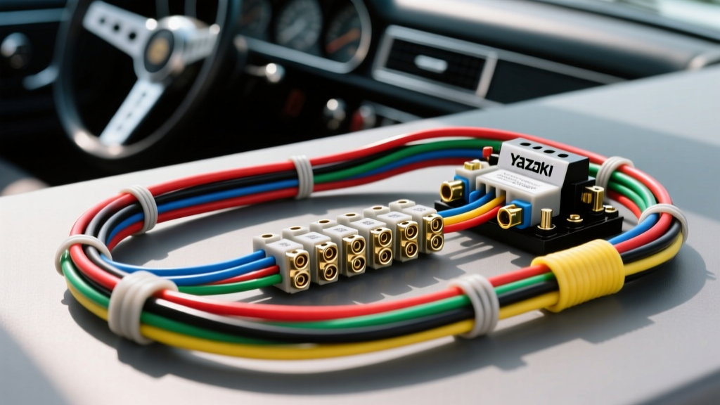
Introduction to JP Auto Electric Architecture
When diagnosing Japanese Domestic Market (JDM) and global Japanese vehicles (Toyota, Honda, Nissan, Subaru), technicians must adapt to specific JP auto electric standards. Unlike European or American architectures that often rely on DIN standards or SAE-centric node naming, JP auto electric systems utilize unique alphanumeric grid systems, metric wire gauges, and proprietary connector families (primarily Yazaki and Sumitomo). This complete wiring diagram walkthrough will decode these schematics, providing actionable data for circuit tracing, pinout identification, and harness repair.
Decoding the Grid: JP Schematic Layouts
Japanese wiring diagrams, particularly those from Toyota and Lexus, map the vehicle harness onto an alphanumeric grid. The vertical axis uses letters (A, B, C) and the horizontal axis uses numbers (1, 2, 3). A splice or connector labeled A14 tells the technician exactly where to probe on the physical diagram page, but it also correlates to physical harness routing zones in the vehicle.
Connector Naming Conventions
In a standard JP auto electric schematic, connectors are identified by a letter-number combination indicating their physical location and mating half:
- A, B, C: Engine compartment connectors.
- D, E, F: Dashboard and cowl connectors.
- G, H, J: Body and floor pan connectors.
- 1A, 1B, 2A: ECU and module specific connectors (e.g., 1A represents the first connector on the ECU, Pin A).
Understanding this nomenclature is critical. If a diagram shows a fault at connector E4, you are looking for a dashboard-to-body ground junction, typically located behind the lower kick panel, rather than an ECU pin.
JP Auto Electric Wire Color & Gauge Standards
Japanese manufacturers use metric cross-sectional area (mm²) for wire sizing, which requires conversion to American Wire Gauge (AWG) for North American technicians selecting repair wire. Furthermore, JP wire color codes use a two-letter system where the first letter is the base color and the second is the tracer (stripe).
Metric to AWG Conversion & Color Code Table
| Metric (mm²) | Approx. AWG | Common Application | JP Color Code Examples |
|---|---|---|---|
| 0.50 mm² | 20 AWG | Sensor signals, CAN bus | L (Blue), V (Violet) |
| 0.85 mm² | 18 AWG | Relay coils, low-draw lighting | B-W (Black/White tracer) |
| 1.25 mm² | 16 AWG | Ignition feeds, injector power | B-Y (Black/Yellow tracer) |
| 2.00 mm² | 14 AWG | Main relay feeds, high-draw circuits | W-B (White/Black tracer) |
| 3.00 mm² | 12 AWG | Battery feeds, starter solenoid | W (Solid White) |
| 5.00 mm² | 10 AWG | Main alternator output, high-current grounds | B (Solid Black) |
Note: Always reference SAE J1128 standards for high-temperature under-hood wiring replacements to ensure the insulation matches JP OEM specifications.
Complete Walkthrough: Toyota EFI Main Relay Circuit
To demonstrate how to read a JP auto electric diagram, we will trace the Electronic Fuel Injection (EFI) Main Relay circuit, a foundational architecture in Toyota/Lexus engine management systems. This walkthrough assumes a standard 12V negative-ground system utilizing a standard 5-pin ISO-style relay mapped to JP schematic symbols.
- Battery to Fusible Link: Power leaves the battery positive terminal via a 3.0mm² (12 AWG) White (W) wire. It passes through the MAIN fusible link (typically 40A-60A) located in the under-hood fuse block.
- Fusible Link to EFI Fuse: The circuit continues as a 2.0mm² (14 AWG) Black-White (B-W) wire to the 15A EFI fuse in the engine compartment relay block.
- EFI Fuse to Relay Pins 1 & 3: Exiting the fuse, the B-W wire splits. One branch feeds Pin 1 (Relay Coil Power), and the thicker branch feeds Pin 3 (Relay Switch Power). Diagnostic Tip: If you have 12V at Pin 3 but not Pin 1, check for a micro-fracture in the B-W wire near the fuse block vibration zone.
- Ignition Switch Trigger (IG1): When the key is turned to ON, the IG1 contact closes. Power flows via a 1.25mm² (16 AWG) Black-Yellow (B-Y) wire to Pin 2 (Relay Coil Ground/Trigger). In modern JP architectures, this wire routes directly to the ECU pin labeled
IGSW(Ignition Switch). The ECU reads this voltage to wake up its internal processors. - ECU Grounding the Coil: The ECU does not ground the coil directly. Instead, the relay coil ground is managed by the ECU's internal transistor, completing the circuit to the ECU's internal E1 ground plane. This allows the ECU to monitor coil current and detect relay coil shorts.
- Relay Switch Output (Pin 5): Once the coil is energized, the internal switch closes. Power flows from Pin 3 to Pin 5 via a 2.0mm² (14 AWG) Black-Red (B-R) wire. This B-R wire feeds the ECU pins labeled
+Band+B2, providing the high-current memory and injector driver power required for engine operation.
Connector Identification & Pinout Extraction
Japanese vehicles heavily rely on Yazaki and Sumitomo connector families. The most common are the Yazaki 090 series (for standard sensors and 10A-15A circuits) and the Sumitomo TS (Thin Small) series for high-density ECU connectors.
Understanding JP Pin Clocking
Unlike American connectors that often number pins sequentially left-to-right, JP auto electric connectors use a "clocking" or matrix numbering system. On a 4-row ECU connector, pins are numbered vertically down each column, then move to the next column. Always verify pin 1 by locating the raised triangular mold mark on the plastic connector housing, not by guessing based on wire color.
Terminal Extraction and Repair
When repairing a JP harness, never use generic flathead screwdrivers to extract pins. Yazaki 090 series terminals require specific twin-prong extraction tools (such as the TE Connectivity AMP 91936-1 or equivalent JIS-specific extractors) to depress the dual micro-lances on the terminal without destroying the plastic housing cavity. If a cavity is damaged, the terminal retention force drops below the OEM 15N minimum, leading to intermittent open circuits under engine vibration.
Common Harness Failure Points in Japanese Vehicles
Injector Resistor Pack Failures (Early 90s JDM)
In older JP auto electric systems (such as the Nissan SR20DET or Toyota 2JZ-GTE non-VVTi), high-impedance injectors were not used. Instead, low-impedance injectors (approx. 2.5 ohms) were paired with a ballast resistor pack mounted on the firewall. Diagnostic Path: If you experience random misfires under high load, measure the voltage drop across the resistor pack. A healthy pack will drop 4V-6V at idle. If one channel shows a 10V+ drop, the internal ceramic resistor has fractured due to thermal cycling. Bypassing the pack to install high-impedance injectors requires reprogramming the ECU injector dead-time latency tables.
Ground Distribution (E1/E2) Corrosion
Japanese schematics designate grounds with specific prefixes: E for Engine/ECU grounds, A for Body/Chassis grounds, and G for Generator/Alternator grounds. The most critical is the E1 ground, which ties the ECU logic ground to the cylinder head.
Real-World Failure Mode: On Honda K-series and Toyota GR engines, the E1 ground strap is often located near the thermostat housing or lower timing cover. Coolant vapor and road salt cause galvanic corrosion between the copper ring terminal and the aluminum block. This creates a high-resistance ground, causing the ECU to see false O2 sensor voltages (running artificially rich) and erratic TPS readings. Always perform a voltage drop test from the ECU metal casing to the battery negative terminal; any reading above 0.05V with the engine running indicates a compromised E1/E2 ground node.
Multiplex Communication: BEAN and AVC-LAN
Modern JP auto electric diagrams include multiplex communication buses. Toyota's proprietary BEAN (Body Electronics Area Network) and AVC-LAN (Audio Visual Communication) operate at much lower voltages and different topologies than standard CAN bus. When diagnosing a parasitic draw caused by a module failing to sleep, refer to the schematic's multiplex section. You must isolate the BEAN bus transceivers (often integrated into the multiplex network door control receivers) by pulling the specific MPX-B fuse, as these networks will keep the ECU awake if a door courtesy switch diode fails in a shorted state.
Mastering JP auto electric diagrams requires shifting away from domestic wiring assumptions. By respecting metric gauges, understanding alphanumeric grid mapping, and utilizing correct JIS extraction tooling, technicians can accurately diagnose and repair complex Japanese electrical architectures with confidence. For further OEM schematic access, technicians should utilize subscriptions to platforms like the Toyota Technical Information System (TIS) or equivalent JDM service portals.