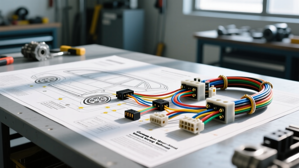
Introduction to the Glendale Auto Electric and Mechanical Methodology
When tackling complex parasitic draws, intermittent stalling, or crank-no-start conditions, the diagnostic philosophy championed by Glendale Auto Electric and Mechanical serves as a gold standard for integrating electrical theory with mechanical reality. Too many technicians treat wiring diagrams as mere maps of wire colors, ignoring the physical environment, mechanical loads, and thermal dynamics that dictate electrical behavior. This complete wiring diagram walkthrough applies the rigorous Glendale Auto Electric and Mechanical methodology to one of the most critical systems in modern internal combustion vehicles: the Electronic Fuel Injection (EFI) Main Relay and Fuel Pump Circuit.
By tracing this circuit from the battery positive post to the fuel pump module ground, we will explore power distribution, pulse-width modulation (PWM) control, voltage drop thresholds, and the mechanical factors that cause electrical components to fail prematurely.
Phase 1: Power Distribution and the EFI Main Relay
Every complete wiring diagram walkthrough must begin at the source. In our reference EFI circuit, power originates at the 12V battery positive terminal and travels through a 120-amp main fusible link before reaching the under-hood fuse box. Here, it passes through a dedicated 30-amp mini-fuse labeled 'EFI MAIN'.
According to the SAE J1128 Low Tension Primary Cable Standard, the wire gauge and insulation type must match the thermal environment of the engine bay. The feed wire from the fuse to the EFI relay Pin 30 is a 10 AWG Red wire with cross-linked polyethylene (XLPE) insulation, rated for continuous 125°C operation. A common failure mode identified in the Glendale Auto Electric and Mechanical archives is the use of standard PVC-insulated wire in this location, which melts and shorts against the exhaust heat shield.
EFI Relay Pinout and Wire Gauge Specifications
The EFI Main Relay is a standard ISO mini-relay. Understanding the exact pin configuration is mandatory for accurate multimeter testing. Below is the specification chart for the relay socket:
| Relay Pin | Wire Color | AWG Size | Circuit Function | Voltage Spec (Key On) |
|---|---|---|---|---|
| Pin 30 | Red | 10 AWG | Constant B+ from EFI Fuse | 12.4V - 12.6V |
| Pin 87 | Grey | 12 AWG | Load Feed to Fuel Pump (+) | 0V (Relay Open) / 12.2V (Closed) |
| Pin 86 | Pink/Black | 14 AWG | Ignition Switch 12V Feed | 12.4V (Key On/Run) |
| Pin 85 | Dark Green/White | 14 AWG | PCM Low-Side Ground Control | 12.4V (Open) / <0.1V (Closed) |
Phase 2: Control Side and PCM Integration
The control circuit dictates when the relay engages. Pin 86 receives 12V from the ignition switch when the key is in the 'Run' or 'Start' position. Pin 85 is wired directly to the Powertrain Control Module (PCM). The PCM utilizes an internal low-side driver (an NPN transistor) to complete the ground path for the relay coil.
When the PCM grounds Pin 85, current flows through the relay's internal electromagnetic coil (typically 65 to 85 ohms of resistance). This generates a magnetic field that pulls the internal contact arm, bridging Pin 30 and Pin 87. A critical component often overlooked in basic diagram reading is the internal flyback diode. When the PCM opens the ground circuit, the collapsing magnetic field creates a high-voltage reverse spike. The flyback diode safely recirculates this spike, protecting the PCM's delicate internal transistor. If an aftermarket relay lacking this diode is installed, the voltage spike can instantly fry the PCM fuel pump driver.
Phase 3: The Load Circuit and Mechanical Integration
The Glendale Auto Electric and Mechanical approach emphasizes that electrical faults are frequently symptoms of mechanical restrictions. Once the relay contacts close, high current flows from Pin 30 to Pin 87, traveling down a 12 AWG Grey wire toward the rear of the vehicle to the fuel pump module.
At the fuel tank, the wiring transitions through a Delphi/Aptiv Metri-Pack 280 series weatherproof connector. This connector uses silver-plated terminals to resist galvanic corrosion caused by road salt and moisture. The power wire enters the fuel pump module, passes through the internal fuel level sender card, and powers the DC brushless fuel pump motor.
The ground side of the fuel pump (12 AWG Black wire) exits the tank and is secured to the chassis at Ground Point G102. The mechanical reality of G102 is crucial: it is often located near the rear axle, exposed to water and debris. If the ground ring terminal suffers from fretting corrosion, resistance increases. According to Ohm's Law, as resistance increases, the fuel pump motor will draw higher amperage to maintain its wattage output, eventually overheating the 12 AWG Grey feed wire or tripping the PCM's internal over-current protection.
Common Failure Modes and Diagnostic Decision Tree
Apply this diagnostic sequence when facing a 'Crank, No Start' condition with zero fuel rail pressure:
- Step 1: Verify Mechanical Baseline. Ensure the fuel tank has adequate volume and the mechanical fuel filter is not clogged. A clogged filter forces the pump to dead-head, spiking electrical amperage.
- Step 2: Listen for Relay Actuation. Turn the key to 'Run'. You should hear the EFI relay click for 2-3 seconds (PCM prime cycle). If no click, proceed to Step 3.
- Step 3: Control Circuit Voltage Drop. Connect a digital multimeter (DMM) in DC millivolt mode. Place the red lead on Pin 86 and the black lead on Pin 85 during the prime cycle. A reading above 200mV indicates excessive resistance in the coil circuit or a failing PCM driver.
- Step 4: Load Circuit Voltage Drop. If the relay clicks but the pump doesn't run, back-probe Pin 30 and Pin 87 with the relay engaged. A voltage drop greater than 0.2V across the relay contacts indicates pitted internal contacts. Replace the relay.
- Step 5: Ground Integrity Test. Measure voltage drop from the fuel pump ground wire to the battery negative terminal while cranking. Any reading above 0.1V indicates a corroded G102 chassis ground.
Advanced Splice and Connector Identification
A complete wiring diagram walkthrough is incomplete without addressing how wires are joined. The Bosch Automotive Electrics guidelines strictly prohibit the use of twist-and-tape splice methods in any high-current or engine-bay environment. The Glendale Auto Electric and Mechanical standard requires the use of solder-seal heat shrink connectors (specifically those with dual-wall polyolefin tubing and hot-melt adhesive) for any necessary harness repairs. This ensures a gas-tight seal that prevents moisture wicking, which can cause copper oxide to form and travel under the wire insulation via capillary action.
Furthermore, when tracing diagrams, look for 'splice pack' identifiers (often labeled as SP101, SP204, etc.). These are physical locations where multiple wires of the same circuit color are joined in a single brass crimp barrel, usually wrapped in foam tape and tucked behind the dashboard kick panel or under the carpet. Identifying these physical splice locations saves hours of diagnostic time when a single circuit experiences a localized voltage drop that affects multiple sensors sharing the same 5V reference or ground return.
Conclusion
Mastering the complete wiring diagram walkthrough requires looking beyond the schematic symbols. By adopting the Glendale Auto Electric and Mechanical methodology, technicians learn to correlate wire gauge, connector metallurgy, PCM driver logic, and mechanical loads into a single, cohesive diagnostic strategy. Whether you are chasing a parasitic draw or diagnosing a dead fuel pump, always verify the physical integrity of the circuit against the theoretical perfection of the diagram.