Introduction to the Patrick Auto Electric Upgrade Philosophy
Classic General Motors A-body vehicles (1968-1972 Chevelle, El Camino, GTO, and Cutlass) were engineered during an era when a 40-amp externally regulated alternator and basic incandescent lighting represented the peak of electrical demand. Today, restomod builders routinely install electronic fuel injection (EFI) systems, electric cooling fans, and high-output audio amplifiers that easily exceed 100 amps of continuous draw. When tackling these high-amperage EFI conversions and accessory additions, many professional restomod shops look to the Patrick Auto Electric methodology as the gold standard for completely overhauling classic GM chassis wiring.
The core philosophy behind the Patrick Auto Electric upgrade protocol focuses on three critical pillars: eliminating high-resistance factory bulkhead connectors, upgrading main feed wire gauges to handle modern high-output alternators, and isolating high-draw accessories on dedicated marine-grade relay circuits. By abandoning the factory ammeter shunt design and utilizing SAE-specification cross-linked wiring, builders can eradicate the voltage drops and fire hazards inherent in 50-year-old PVC-insulated harnesses.
Core Components and Wire Sizing Specifications
Before cutting a single factory wire, it is imperative to select the correct automotive primary wire. The Patrick Auto Electric standard strictly prohibits the use of standard PVC-insulated wire for engine bay routing due to its low melting point and poor abrasion resistance. Instead, upgrades must utilize SXL (Cross-Linked) or GXL wire, which complies with the SAE J1128 standard for high-temperature engine compartment environments.
| Circuit Application | Recommended AWG | Wire Type | Max Continuous Ampacity (Engine Bay) |
|---|---|---|---|
| Main Battery to Starter / Alt Feed | 4 AWG or 2 AWG | SXL Cross-Linked | 120A - 150A |
| Alternator Sense & Exciter | 12 AWG | GXL Thin-Wall | 15A |
| Headlight Feeds (via Relay) | 10 AWG | GXL Thin-Wall | 30A |
| Ignition Switched (Pink) | 12 AWG | GXL Thin-Wall | 15A |
| Dash Illumination (Brown) | 14 AWG | TXL Extra-Thin | 10A |
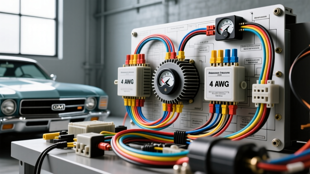
According to data referenced in the Haynes GM A-Body Repair Manual, the factory main feed from the horn relay to the firewall was often a marginal 10 AWG or 12 AWG red wire. The Patrick Auto Electric method mandates replacing this entire feed with a continuous run of 4 AWG SXL red wire, fused at 150A via a marine-grade ANL fuse block mounted directly at the starter solenoid battery post.
Step-by-Step: Bypassing the GM 12-Pin Firewall Bulkhead
The most notorious failure point in classic GM wiring is the 12-pin firewall bulkhead connector. Over decades of thermal cycling, the spade terminals oxidize, increasing resistance and causing the plastic housing to melt—often taking the dash harness with it. The Patrick Auto Electric protocol involves completely bypassing the factory ammeter and bulkhead for high-current paths.
1. Removing the Ammeter Shunt
Factory GM ammeters are wired in series with the main charging circuit. The heavy-gauge wires route from the alternator, through the firewall, into the dash gauge, and back out to the main splice. This creates two massive points of potential resistance. To upgrade, disconnect the battery and remove the heavy red and black wires from the back of the ammeter. Splice them together using a sealed, adhesive-lined heat shrink butt connector, effectively removing the gauge from the high-current path.
2. Installing a Voltmeter
Replace the ammeter with a modern sweep-style voltmeter. Wire the voltmeter's positive terminal to a switched 12V source (typically the factory Pink ignition wire) using 12 AWG wire protected by a 10A ATO fuse. Ground the negative terminal to a clean, unpainted metal dash brace using a ring terminal and a star washer.
3. Rerouting High-Current Feeds
Instead of passing the alternator output through the 12-pin bulkhead, drill a new 1-inch hole in the firewall away from the exhaust headers. Install a rubber firewall grommet and pass the new 4 AWG alternator output wire directly into the engine bay, routing it to a heavy-duty Mega Fuse holder, and then directly to the battery positive terminal or starter solenoid.
High-Output Alternator Relay Harness Integration
When upgrading from a factory 10SI (63-amp) alternator to a 12SI or modern 1-wire 100A+ alternator, the factory resistance wire and warning light circuit are insufficient for proper field excitation. The Patrick Auto Electric method utilizes a dedicated 4-pin Bosch-style relay to manage the alternator's exciter and sense circuits, ensuring the alternator receives a clean, unswitched 12V reference signal.
| Relay Terminal | Function | Wire Color / Gauge | Connection Point |
|---|---|---|---|
| 30 (Common) | Main Power In | Red / 10 AWG | Fused 12V Battery Source |
| 87 (Normally Open) | Switched Power Out | Brown / 12 AWG | Alternator Terminal 1 (Exciter) |
| 85 (Coil Ground) | Relay Ground | Black / 14 AWG | Engine Block / Clean Chassis |
| 86 (Coil Power) | Trigger Signal | Pink / 14 AWG | Ignition Switch 'Run' Terminal |
Terminal 2 (Sense Wire) Routing: The sense wire dictates the alternator's voltage regulation. If connected directly to the alternator output post, the alternator will compensate only for the voltage at the alternator, not the battery. The Patrick Auto Electric standard requires running a dedicated 12 AWG white sense wire from Alternator Terminal 2 directly to the positive battery post or the main distribution busbar, ensuring the system maintains exactly 14.2V at the battery regardless of accessory load.
Auxiliary Fuse Block Integration for EFI and Electric Fans
Classic fuse boxes lack the circuit capacity for modern electric cooling fans (which can draw 25-30 amps each on startup) and EFI fuel pumps. The modification project requires mounting a secondary 6-circuit or 12-circuit marine-grade fuse block in the engine bay or under-dash kick panel.
When wiring electric fans, never route the high-amperage draw through the factory dash switches or the horn relay. Instead, use the ignition-switched Pink wire to trigger a pair of 40A Bosch-style relays (one for each fan). The main power for the fan relays (Terminal 30) must come directly from the new 4 AWG main distribution busbar, protected by 30A circuit breakers. This ensures that the high inrush current of the fan motors does not backfeed into the delicate EFI ECU wiring or cause voltage spikes that can corrupt fuel injector pulse-width signals.
Post-Upgrade Troubleshooting and Voltage Drop Testing
Even with meticulous adherence to the Patrick Auto Electric methodology, poor crimping or hidden corrosion can cause issues. After completing the upgrade, perform a systematic voltage drop test using a digital multimeter (DMM).
- Alternator Output to Battery Positive: With the engine running at 2000 RPM and headlights on, place the red DMM probe on the alternator output post and the black probe on the battery positive post. A reading greater than 0.2V indicates excessive resistance in the 4 AWG feed wire or a poor crimp at the Mega Fuse holder.
- Engine Block to Battery Negative: Place the red probe on the battery negative and the black probe on the alternator casing. A reading above 0.1V indicates a failing engine ground strap. Upgrade the factory braided strap to a 2 AWG flat ground cable bolted directly to the cylinder head and chassis.
- Ignition Switch to Coil/ECU: Measure voltage at the EFI ECU main power pin during cranking. If it drops below 9.5V, the ignition switch contacts are worn. Install a secondary starter solenoid relay (commonly known as a Ford fender relay) to bypass the factory ignition switch for the EFI main relay trigger.
For further reference on proper crimping standards and terminal retention forces for Weather-Pack and Metri-Pack 280 connectors, consult Delphi Connection Systems technical bulletins. By following this comprehensive upgrade and modification protocol, your classic GM vehicle will possess an electrical architecture capable of supporting modern performance demands while maintaining absolute reliability and fire safety.