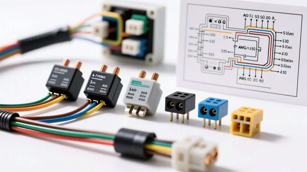
Understanding Auto Electrical Relay Architectures
Selecting the correct auto electrical relays is critical for managing high-current loads while protecting sensitive low-current control circuits. At their core, automotive relays are electromagnetic switches. A low-current signal energizes a copper wire coil, creating a magnetic field that pulls a steel armature to close or open high-current contacts. This isolation prevents heavy amperage from routing through dashboard switches or Engine Control Units (ECUs), mitigating voltage drop and preventing thermal failures.
When upgrading vehicle lighting, installing electric AC compressors, or wiring auxiliary fuel pumps, choosing the wrong relay form factor or pin configuration can lead to melted fuse boxes, parasitic battery drains, or catastrophic PCM (Powertrain Control Module) damage. This guide breaks down the engineering specifications, ISO standards, and selection criteria required for professional-grade automotive wiring.
ISO Form Factor Comparison
The automotive industry standardized relay footprints under ISO 7588 to ensure cross-compatibility between manufacturers. However, variations exist based on current requirements and spatial constraints within modern fuse boxes.
| Relay Type | ISO Standard | Dimensions (mm) | Max Continuous Current | Terminal Width | Common Applications |
|---|---|---|---|---|---|
| ISO Mini (Standard) | ISO 7588-2 | 25.4 x 25.4 x 25.4 | 30A - 40A | 6.3mm (1/4 inch) | Horn, fuel pump, headlights, cooling fans |
| ISO Micro | ISO 7588-3 | 12.5 x 15.0 x 25.4 | 20A - 30A | 4.8mm or 6.3mm | Interior lighting, power windows, ECU triggers |
| ISO Maxi (High Current) | ISO 7588-2 (Extended) | 28.5 x 28.5 x 40.0 | 50A - 70A | 9.5mm (3/8 inch) | Starter solenoids, heavy winches, glow plugs |
According to SAE International standards, continuous current ratings assume a standard ambient under-hood temperature of 85°C (185°F). If mounting a relay near exhaust manifolds or turbochargers, you must derate the maximum amperage by 20% to prevent contact welding.
DIN 72552 Pinout Configurations: 4-Pin vs. 5-Pin
Automotive relays utilize the DIN 72552 numbering standard to identify terminals. Misunderstanding these pinouts is the leading cause of aftermarket wiring harness failures.
Standard 4-Pin (SPST - Single Pole, Single Throw)
The 4-pin relay acts as a simple on/off switch for a single high-current circuit.
- Pin 85: Coil Ground (or ECU switched ground)
- Pin 86: Coil B+ (12V Ignition or Battery feed)
- Pin 30: Common Terminal (High-current feed from battery via fuse)
- Pin 87: Normally Open (NO) Output (Routes power to the load when energized)
Standard 5-Pin (SPDT - Single Pole, Double Throw)
The 5-pin relay includes a Normally Closed (NC) circuit, allowing power to be routed to one of two different loads depending on the relay's state.
- Pins 85, 86, 30: Identical to the 4-pin configuration.
- Pin 87: Normally Open (NO) Output.
- Pin 87a: Normally Closed (NC) Output. Power flows from Pin 30 to Pin 87a when the relay is de-energized.
Critical Warning: Never plug a 5-pin relay into a 4-pin socket without verifying the socket's wiring. If the vehicle harness has a grounded trace where Pin 87a sits, inserting a 5-pin relay will create a direct short to ground through the NC contacts the moment the relay is de-energized, instantly blowing the main fuse or melting the harness.
Load Calculation and AWG Wire Sizing
A relay is only as reliable as the wire feeding it. The control circuit (coil) and the load circuit (contacts) require vastly different American Wire Gauge (AWG) sizing. The coil typically draws between 120mA and 250mA, while the load circuit can pull upwards of 40A.
Furthermore, wire length dictates voltage drop. A 10-foot run of 12 AWG wire will experience significant voltage drop at 20A, starving components like fuel pumps or HID ballasts of necessary voltage. Always size wire based on the maximum amperage and round up for runs exceeding 8 feet.
| Relay Rating | Max Load Amperage | Load Circuit Wire (Under 8 ft) | Load Circuit Wire (8-15 ft) | Coil Circuit Wire (85/86) |
|---|---|---|---|---|
| 20A Micro | 15A (Continuous) | 14 AWG | 12 AWG | 18 AWG |
| 30A Mini | 25A (Continuous) | 12 AWG | 10 AWG | 16 AWG |
| 40A Mini | 30A (Continuous) | 10 AWG | 8 AWG | 16 AWG |
| 60A Maxi | 50A (Continuous) | 8 AWG | 6 AWG | 14 AWG |
Flyback Suppression and ECU Protection
In modern vehicles, the ECU or Body Control Module (BCM) often controls the relay by switching the ground path on Pin 85. When the ECU cuts the ground, the magnetic field in the relay coil collapses rapidly. This collapse generates a high-voltage reverse polarity spike (flyback voltage) that can exceed 100V.
Without suppression, this spike travels backward into the ECU, instantly destroying the internal driver transistor. When selecting auto electrical relays for PCM-switched circuits, you must choose a relay with built-in suppression.
- Resistor Suppressed: Uses an internal resistor to bleed off the spike. Polarity insensitive (Pins 85 and 86 can be swapped). Safe for older mechanical switches and basic ECUs.
- Diode Suppressed: Uses an internal flyback diode to recirculate the spike. Highly effective but strictly polarity sensitive. Pin 86 must be B+ and Pin 85 must be the ECU ground. If wired backward, the diode will short the circuit and blow the control fuse.
For deep technical specifications on semiconductor protection in automotive environments, refer to the Littelfuse Automotive Relay Selection Guide.
Weatherproofing and Connector Selection
For under-hood or chassis-mounted applications, standard 1/4-inch spade terminals are insufficient due to moisture intrusion and vibration-induced fretting corrosion. Professional installations require sealed connector systems.
- TE Connectivity AMP MATE-N-LOK: Excellent for high-current battery feeds (Pin 30) using 10 AWG or 8 AWG wire.
- Delphi Metri-Pack 280: The industry standard for sealed 4-pin and 5-pin relay harnesses. Features secondary locking mechanisms (TPA) to prevent terminals from backing out under heavy vibration.
- Deutsch DT Series: Ideal for extreme environments (off-road, marine, heavy diesel). Uses solid thermoplastic housings and silicone rear wire seals.
Selection Decision Tree: Matching the Relay to the Application
Use this diagnostic tree to specify the exact relay required for your wiring project:
- What is the continuous amperage of the load?
- Under 20A: Select ISO Micro.
- 20A to 35A: Select ISO Mini (Standard).
- Over 35A: Select ISO Maxi or a solid-state contactor.
- Does the circuit require dual routing (e.g., switching from low beam to high beam, or locking to unlocking)?
- Yes: Select 5-Pin (SPDT).
- No: Select 4-Pin (SPST).
- Is the coil triggered by a solid-state ECU/BCM ground driver?
- Yes: Select a relay with an internal flyback diode (ensure correct Pin 85/86 polarity) or an internal resistor.
- No (Triggered by a mechanical dashboard switch): A standard unsuppressed relay is acceptable.
- Is the relay mounted in a high-vibration or wet environment?
- Yes: Use a bracket-mounted relay with a sealed Metri-Pack or Deutsch harness pigtail. Avoid plugging directly into an unsealed fuse box.
Diagnostic Testing and Failure Modes
When troubleshooting a suspected relay failure, rely on a digital multimeter (DMM) rather than guesswork. According to HELLA Technical Diagnostics, relays typically fail in three ways: open coil, welded contacts, or high-resistance carbon tracking.
Step-by-Step Bench Testing
- Test the Coil (Pins 85 & 86): Set the DMM to Ohms (Ω). Place probes on 85 and 86. A healthy 12V automotive relay will read between 65Ω and 90Ω. A reading of 'OL' (Open Line) indicates a broken internal copper winding. A reading near 0Ω indicates a shorted coil.
- Test the Contacts (Pins 30 & 87): Set the DMM to Continuity or Ohms. Place probes on 30 and 87. It should read 'OL' (open). If it shows continuity while de-energized, the contacts are welded shut from a previous over-current event.
- Energize and Verify: Apply 12V to Pin 86 and ground to Pin 85. You should hear a distinct mechanical click. The DMM across Pins 30 and 87 should now read near 0.0Ω. If the resistance fluctuates or reads above 0.5Ω, the internal contacts suffer from carbon pitting and the relay must be replaced.
By adhering to these ISO standards, AWG sizing charts, and pinout protocols, you ensure that your vehicle's electrical architecture remains robust, safe, and capable of handling demanding aftermarket accessories without compromising the factory wiring harness.