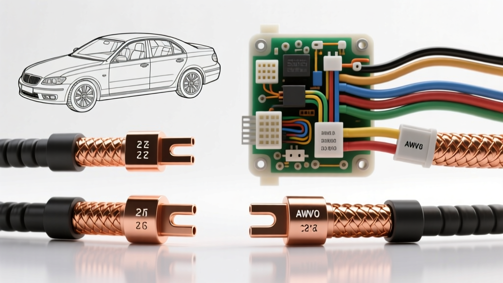
Mr Auto Electric Specialist Rates vs. DIY Wiring Costs
When electrical gremlins strike a modern vehicle, owners face a critical decision: pay the premium diagnostic rates at a dedicated Mr Auto Electric specialist shop, or invest in the capital equipment required to diagnose and repair the wiring harness at home. Modern automotive electrical architecture is no longer limited to simple 12V DC relay circuits. Today's vehicles utilize high-speed CAN-bus networks, LIN-bus alternator controls, and high-amperage 48V mild-hybrid systems. A specialist auto electrician typically charges between $140 and $185 per hour for diagnostic time. While this yields expert results, the cumulative cost of diagnosing a parasitic draw, repairing a frayed CAN-bus twisted pair, and replacing a high-current alternator B+ cable can easily exceed $1,500 in labor alone.
This analysis breaks down the exact tool requirements, capital investments, and technical specifications needed to perform professional-grade automotive electrical diagnostics and repairs in a home garage. By comparing the hidden costs of DIY consumables against professional shop rates, we can determine the true ROI of mastering auto electrical systems.
Essential Diagnostic Tool Tiers & Capital Requirements
To safely and accurately diagnose modern vehicle networks, a digital multimeter (DMM) is no longer sufficient. You must be able to read pulse-width modulation (PWM) signals and serial data buses. Below is the capital investment required for three tiers of DIY electrical diagnostics, benchmarked against professional Mr Auto Electric shop equipment.
| Tool Tier | Core Equipment | Estimated Cost | Diagnostic Capabilities |
|---|---|---|---|
| Tier 1: Basic | Fluke 115 DMM, basic wire strippers, test light | $250 - $350 | Continuity, basic voltage drop, fuse testing, simple relay logic |
| Tier 2: Advanced | Fluke 87V, Power Probe IV, basic crimpers | $900 - $1,200 | Min/Max recording, PWM duty cycle, component actuation, parasitic draw |
| Tier 3: Master | PicoScope 4425A, Fluke 88V, OEM breakout boxes | $3,000 - $4,500 | CAN-bus decoding, LIN-bus alternator mapping, injector ramping, network topology |
According to Fluke Automotive Testing Guidelines, a True-RMS multimeter with a minimum 10-Megohm input impedance is mandatory for testing sensitive ECM and TCM circuits without damaging solid-state components. However, for multiplex networks, an automotive oscilloscope like the PicoScope is required to visualize the physical layer of the network.
Case Study: Diagnosing a LIN-Controlled Alternator
Consider a scenario where a vehicle's battery is chronically undercharging. A traditional internally regulated alternator simply requires a 12V ignition feed and a sense wire. Modern alternators, however, use a Local Interconnect Network (LIN) bus to communicate directly with the Engine Control Module (ECM). If you take this to a Mr Auto Electric shop, they will likely hook up a scope to verify the square-wave data signal.
Take the common GM 4-pin Delphi Packard alternator connector as an example. The pinout and wire color codes are highly specific:
- Pin A (L): LIN-bus data / Lamp circuit. Typically a Brown or Gray wire. Carries a 12V square-wave PWM signal from the ECM.
- Pin B (I): Ignition 1 feed. Typically a Pink wire. Provides initial rotor excitation.
- Pin C (S): Battery Sense. Typically a Red 18 AWG wire, fused directly to the B+ junction block. Reads actual battery post voltage.
- Pin D (F): Field / PWM output. Typically a White wire. Sends a duty-cycle signal back to the ECM to indicate alternator load, used for cooling fan ramp-up and idle speed stabilization.
If a DIYer uses a standard multimeter on Pin A, they will read an 'averaged' voltage of roughly 7V to 9V and incorrectly assume the wire is shorted or the ECM is failing. A professional uses an oscilloscope to verify the 0V to 12V square wave, checking for clean vertical edges and absence of electromagnetic interference (EMI). As noted in SAE network standards, signal degradation on LIN or CAN buses due to poor shielding or terminal fretting will cause the ECM to default the alternator to a fixed 13.8V output mode, triggering a hidden undercharge condition.
Consumables and Crimping: The Hidden DIY Expenses
Diagnostic tools represent only half the battle. The physical repair of automotive wiring requires specialized consumables that professional shops buy in bulk, but DIYers must purchase in expensive starter kits. The most common failure point in high-current circuits is a poorly crimped terminal leading to thermal runaway and melted connector housings.
High-Current Starter & Alternator Circuit Upgrades
When upgrading an alternator to a 250A high-output unit for off-road or overland applications, the factory 4 AWG or 6 AWG B+ cable is insufficient and will cause a severe voltage drop. Upgrading this circuit requires specific materials and heavy-duty tooling:
- Wire: 1/0 AWG (53.5 mm²) fine-strand copper welding cable. This provides the necessary flexibility and current-carrying capacity (rated for 250A+ continuous in engine bay temperatures).
- Terminals: 1/0 AWG closed-barrel copper ring terminals with a 5/16' or 3/8' stud hole.
- Crimping Tool: A standard hand crimper will not achieve the necessary cold-weld compression. You must invest in a 6-ton hydraulic crimper with hexagonal dies to ensure the terminal and wire deform uniformly, eliminating air pockets where corrosion can start.
- Insulation: 3M FP-301 heat shrink tubing with a 3:1 shrink ratio and internal adhesive lining to seal out moisture and battery acid.
- Protection: 250A ANL fuse and CNC-machined fuse holder mounted within 18 inches of the battery positive post.
The capital cost for a hydraulic crimper, heavy-duty wire strippers, and an assortment of 1/0 AWG terminals and heat shrink easily exceeds $350. Furthermore, performing a proper voltage drop test on the newly built circuit requires measuring across the entire length of the cable while the engine is cranking or under heavy electrical load. The Pico Technology automotive diagnostics library dictates that a healthy high-current B+ cable should exhibit less than 0.1V of drop per connection point, and no more than 0.5V total drop across the entire positive circuit under maximum load.
Parasitic Draw & Multiplex Network Troubleshooting
Parasitic draws are the bane of auto electrical diagnostics. Modern vehicles feature dozens of modules that must 'go to sleep' on the CAN-bus before the vehicle reaches its target quiescent current draw (typically between 20mA and 50mA). If a single module fails to sleep, or if a door-ajar switch circuit is shorted, the battery will drain overnight.
To diagnose this, professionals use a low-amp current clamp (like the Fluke i410) paired with an oscilloscope to monitor the draw over a 45-minute sleep cycle without breaking the circuit. Breaking the circuit with a multimeter in series can cause modules to wake up, resetting the sleep timer and leading to false diagnostics. Furthermore, testing the CAN-bus termination resistance requires accessing the OBD2 Data Link Connector (DLC). Pins 6 (CAN-High) and 14 (CAN-Low) should read exactly 60 ohms of resistance with the battery disconnected, representing the two 120-ohm termination resistors in parallel at opposite ends of the network bus. Backprobing these pins with standard paperclips or thick multimeter probes will permanently spread the delicate female terminals inside the DLC, causing intermittent communication failures. Professionals use specific T-pin backprobes or DLC breakout boxes to preserve terminal integrity.
ROI Calculation: When to Call the Professional
So, when does the DIY approach make financial sense compared to hiring a Mr Auto Electric specialist? If your vehicle requires a simple alternator sense wire repair, a starter solenoid voltage drop test, or a basic parasitic draw isolation using the fuse-pull method, the Tier 1 and Tier 2 tool investments will pay for themselves after a single job. The cost of a Fluke 87V and a proper set of Weather-Pack crimpers is easily recouped by avoiding a $200 diagnostic fee and $150 markup on a dealer pigtail harness.
However, if the diagnosis requires flashing a new Body Control Module (BCM), decoding a corrupted FlexRay network, or tracing a short-to-ground deep inside a factory sealed wiring harness loom behind the dashboard, the Tier 3 tool requirements and the sheer time investment make professional intervention the logical choice. Understanding the exact specifications, wire colors, and pin configurations of your vehicle's electrical architecture is the first step in making that critical cost-benefit decision.