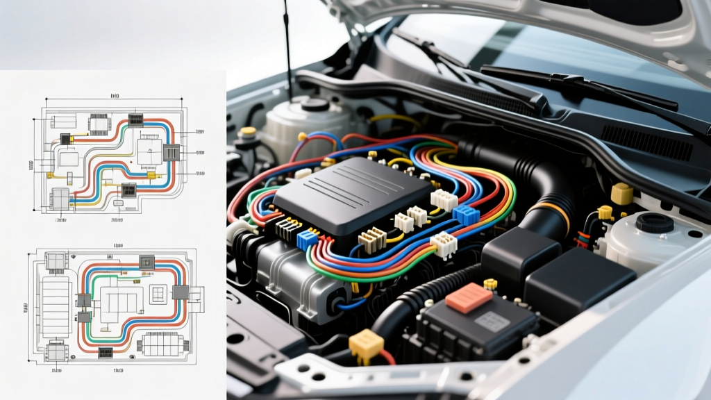
The Evolution of Automotive Electrical Architecture
Modern vehicles are no longer simple machines with basic 12-volt direct current (DC) loops. Today's automotive electrical systems rely on complex multiplexed networks, including Controller Area Network (CAN), Local Interconnect Network (LIN), and FlexRay protocols. When an electrical fault occurs—ranging from a parasitic battery draw to a failed alternator regulator—vehicle owners face a critical decision: should they rely on a franchise dealership or seek out an independent specialist? This guide evaluates the technical capabilities, repair methodologies, and diagnostic standards of professional electrical shops, using Randy Auto Electric Repair Inc as a benchmark for top-tier independent service centers compared to traditional dealership service departments.
Service Methodology: Component Repair vs. Assembly Replacement
The most significant difference between a dealership and a dedicated auto electric specialist lies in the repair philosophy. Dealership technicians are often bound by manufacturer warranty protocols and flat-rate labor guides that favor complete assembly replacement. If a dealership diagnostic tool flags a fault in the Engine Control Module (ECM) wiring harness, the standard procedure is to replace the entire harness—an operation that can cost thousands of dollars and require removing the dashboard or engine.
In contrast, specialized facilities like Randy Auto Electric Repair Inc focus on component-level diagnostics and targeted circuit repair. By utilizing advanced oscilloscopes and time-domain reflectometers (TDR), independent electrical experts can isolate a broken copper strand, a corroded terminal inside a connector, or a short-to-ground within a specific 18 AWG sensor wire. This targeted approach not only saves the consumer significant money but also preserves the factory integrity of the vehicle's main wiring looms.
Connector and Terminal Level Intervention
True electrical specialists do not rely on generic butt connectors and electrical tape. When repairing a severed wire leading to an oxygen sensor or a fuel injector, professionals adhere to strict automotive wiring standards. For example, when working with sealed connectors like the Molex MX150 or TE Connectivity AMP Superseal series, specialists use precise pin extraction tools to remove the damaged terminal. They then crimp a new OEM-style terminal using a ratcheting crimp tool calibrated to the exact wire gauge (typically 18 to 20 AWG for sensor circuits), ensuring the wire brush crimp achieves optimal pull-out force without damaging the copper strands. Finally, the connector cavity is resealed with dielectric grease and a new silicone plug to maintain IP67 waterproof ratings.
Network Diagnostics: CAN Bus and LIN Bus Integrity
Drivability issues and phantom warning lights are frequently caused by network communication failures. A standard OBD-II code reader might only output a generic U0100 (Lost Communication with ECM/PCM) code. A dealership might respond by flashing the module or replacing it outright. However, an expert at Randy Auto Electric Repair Inc will immediately hook up a 4-channel Picoscope to map the physical layer of the network.
- CAN Bus Topology: High-speed CAN (ISO 11898-2) operates using a twisted pair of wires (CAN-High and CAN-Low) with a characteristic impedance of 120 ohms. Specialists verify the terminating resistors at the ends of the bus and check for symmetry in the voltage waveforms (CAN-H dominant at ~3.5V, CAN-L dominant at ~1.5V).
- Wire Color Codes & Pinouts: While colors vary by OEM, CAN wires are typically found on OBD-II pins 6 (CAN-H) and 14 (CAN-L). In many Chrysler and Ford applications, these are Orange/White and Orange/Black, or Green/White and Green/Black. Splicing these wires requires ultrasonic welding or specialized parallel crimp sleeves; standard twisting and soldering can alter the characteristic impedance, causing signal reflection and data packet loss.
- LIN Bus Alternator Control: Many modern alternators use a single-wire LIN bus connection from the ECM to control voltage output. A break in this 20 AWG wire (often Gray or Green) will cause the alternator to default to a base voltage of 13.8V, disabling the Regulated Voltage Control (RVC) system and triggering a battery warning light.
Heavy-Duty Power Distribution and AWG Standards
High-amperage circuits, such as starter motors, glow plug modules, and primary alternator outputs, require strict adherence to American Wire Gauge (AWG) sizing and voltage drop limits. According to SAE J1284 standards, the maximum allowable voltage drop across any single connection or switch is 0.1V, and the total circuit voltage drop should not exceed 0.5V under full load.
| Circuit Application | Recommended AWG | Max Continuous Ampacity | Terminal Type & Torque Spec |
|---|---|---|---|
| Battery to Starter Motor | 1/0 AWG or 2/0 AWG | 150A - 200A | Heavy-Duty Copper Lug, 12-15 Nm |
| Alternator B+ Output | 4 AWG or 2 AWG | 120A - 175A | Ring Terminal (M8/M10), 8-12 Nm |
| Starter Solenoid Trigger | 12 AWG or 10 AWG | 20A - 30A | Spade / Ring, Hand Crimp |
| ECM Main Power Relay | 14 AWG or 12 AWG | 15A - 20A | Weather-Pack / Metri-Pack 280 |
When heavy-gauge cables suffer from terminal corrosion or strand breakage, general mechanics often attempt to patch them with undersized wire or inadequate solder joints. Solder is brittle and lacks the tensile strength required for engine bay vibrations. Specialists like Randy Auto Electric Repair Inc utilize hydraulic or heavy-ratchet crimpers to attach closed-barrel copper lugs, followed by adhesive-lined, dual-wall heat shrink tubing to prevent moisture intrusion and subsequent galvanic corrosion.
Advanced Diagnostic Tooling: Oscilloscopes and Current Clamps
The hallmark of a premier auto electrical repair facility is the use of laboratory-grade oscilloscopes rather than relying solely on digital multimeters (DMM). A DMM averages voltage over time and is virtually useless for diagnosing fast-acting Pulse Width Modulated (PWM) signals. For instance, diagnosing a failing electronic throttle body or a variable valve timing (VVT) solenoid requires viewing the PWM duty cycle and the corresponding inductive kickback spike on a graph. Furthermore, using a low-amp current clamp allows technicians to analyze the parasitic draw signature of a vehicle's CAN bus wake-up sequence, identifying exactly which module is failing to enter sleep mode without having to pull fuses one by one.
Adherence to IPC/WHMA-A-620 Wiring Standards
While not always explicitly advertised, the best independent shops follow the IPC/WHMA-A-620 standard for cable and wire harness assemblies. This standard dictates the exact requirements for soldering, crimping, and heat shrink application in high-reliability environments. It specifies that a proper wire crimp must show the wire strands slightly protruding from the front of the terminal barrel (the "bellmouth") and that insulation must not be pinched inside the conductor crimp. By adhering to these aerospace and automotive-grade standards, specialists ensure that a repaired wire will endure the thermal cycling and high-frequency vibrations inherent in internal combustion and electric vehicle platforms.
Making the Right Selection for Your Vehicle
Choosing between a dealership and an independent expert like Randy Auto Electric Repair Inc ultimately depends on the nature of the fault. If your vehicle requires a proprietary software flash, a security gateway unlock, or a warranty-covered module replacement, the dealership is the necessary route. However, for physical wiring faults, intermittent ground issues, parasitic draws, alternator communication failures, and custom accessory integrations (such as high-amperage electric AC compressors or auxiliary lighting relays), the independent specialist provides superior technical depth. They possess the micro-soldering skills, the pinout schematics, and the diagnostic patience to repair the root cause of the electrical failure rather than simply selling you a brand-new wiring harness.
For further reading on automotive electrical fundamentals and circuit diagnostics, consult the comprehensive guides found in Bosch Automotive Electrics and Automotive Electronics, which remains the industry gold standard for understanding vehicle power distribution and multiplex network theory.