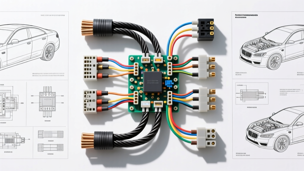
The Cost of Ignoring Auto Electrical Connectors Manufacturers
Modern vehicles contain up to three miles of wiring and over 3,000 individual circuit terminations. When a harness fails, the instinct of many amateur mechanics is to cut out the OEM connector and splice in a generic weather-pack or butt connector. This approach ignores the rigorous engineering performed by top auto electrical connectors manufacturers like TE Connectivity, Aptiv, Yazaki, and Molex. These manufacturers design specific terminal geometries, cavity seals, and locking mechanisms to withstand high-frequency vibrations, thermal cycling, and capillary moisture intrusion.
Using incorrect replacement housings or mismatched terminals leads to fretting corrosion, terminal push-out (backout), and catastrophic voltage drops on high-amperage circuits. This guide provides a step-by-step troubleshooting flow to help you isolate connector-based electrical faults, identify the specific OEM manufacturer family, and execute a permanent, USCAR-compliant repair.
Phase 1: Electrical Symptom Isolation Flowchart
Before sourcing replacement pigtails, you must isolate the physical failure mode within the connector cavity. Follow this decision tree to identify the root cause of the electrical fault.
Branch A: Intermittent CAN Bus or Sensor Dropouts (U-Codes)
- Symptom: Intermittent U0100 (Lost Communication with ECM) or erratic sensor data (e.g., MAF or O2 sensors) without a hard open or short to ground.
- Diagnosis: Fretting corrosion. Micro-vibrations cause the tin-plated terminal surfaces to oxidize, creating a high-resistance diode effect that corrupts low-voltage CAN High/CAN Low square waves.
- Verification: Back-probe the connector and monitor the signal on an oscilloscope while physically manipulating the harness. Look for amplitude dropout or excessive noise floors.
- Manufacturer Solution: Source replacement terminals from the original auto electrical connectors manufacturers that feature gold-plated mating surfaces for low-current data circuits, or apply a specialized dielectric tuning grease (like Nyogel 760G) to disrupt oxide formation.
Branch B: High Resistance / Voltage Drop on Power Circuits
- Symptom: Dim lighting, slow power window operation, or fuel pump starvation under load.
- Diagnosis: Loose terminal crimp or cavity expansion. The wire barrel is no longer compressing the copper strands, or the female terminal tension fingers have yielded due to thermal expansion.
- Verification: Perform a loaded voltage drop test across the mated connector. A reading greater than 50mV on a 5A circuit, or 100mV on a 10A+ circuit, indicates a failed termination.
- Manufacturer Solution: The female terminal must be replaced. Attempting to 'squeeze' the terminal with pliers destroys the secondary locking lance and ruins the mating geometry engineered by the manufacturer.
Branch C: Terminal Push-Out (Backout)
- Symptom: A circuit works when the harness is stationary but fails when the engine torques or the door is slammed.
- Diagnosis: Failure of the primary locking lance or missing Terminal Position Assurance (TPA) wedge.
- Verification: Gently pull back on the wire while the connector is mated. If the terminal retracts into the housing by more than 1mm, the retention mechanism has failed.
- Manufacturer Solution: Replace the housing and ensure the new TPA wedge is fully seated. Never bypass a TPA requirement.
Phase 2: Identifying the OEM Connector Family
To source the correct repair kit, you must identify which of the major auto electrical connectors manufacturers produced the harness side. Below is a reference chart of the most common automotive connector series, their terminal styles, and AWG mappings.
| Manufacturer | Series / Family | Terminal Geometry | AWG Range | Environmental Seal | TPA Required? |
|---|---|---|---|---|---|
| Aptiv (Delphi) | Metri-Pack 150 / 280 | Flat Blade | 22 - 12 AWG | Individual Cavity Plug | Yes (on most) |
| Aptiv (Delphi) | Weather-Pack | Cylindrical Pin/Socket | 18 - 12 AWG | Individual Cavity Plug | No (Primary Lance) |
| TE Connectivity | Superseal 1.5 | Cylindrical Sealed | 22 - 14 AWG | Mat Seal + Cavity Plug | Yes |
| TE Connectivity | Deutsch DT / DTM | Solid Cylindrical | 20 - 14 AWG | Rear Grommet Wedge | Yes (Wedge Lock) |
| Yazaki | YESC (0.64 / 1.2 / 2.8) | Tuning Fork / Blade | 24 - 10 AWG | Mat Seal / Cavity | Yes |
| Molex | MX150 | Cylindrical Sealed | 22 - 14 AWG | Mat Seal | Yes |
Reference Note: Always cross-reference the cavity count and keying rib position. A 4-way Aptiv GT280 connector may have three different keying variations depending on the vehicle manufacturer (GM vs. Stellantis).
Phase 3: Executing a USCAR-2 Compliant Repair
Once you have identified the correct auto electrical connectors manufacturers and sourced the OEM pigtail or loose terminals, you must execute the repair to SAE USCAR-2 (Automotive Electrical Connector System Standard) specifications. Improper crimping is the leading cause of warranty returns in electrical diagnostics.
Step 1: Wire Preparation and Strip Length
Cut the damaged wire back to clean, unoxidized copper. Do not strip the wire until you have measured the terminal barrel. The wire insulation should butt exactly against the wire barrel, and the copper strands should be flush with the end of the conductor crimp barrel. For a standard 18 AWG (0.8mm²) terminal, the strip length is typically 4.0mm to 5.0mm. Use precision wire strippers to avoid nicking the copper strands, which reduces the tensile strength of the wire.
Step 2: The F-Crimp vs. B-Crimp Protocol
Automotive terminals utilize an F-crimp (also known as an open-barrel crimp). When using a high-quality ratcheting crimper (such as the Hozan P-707 or TE Connectivity CERTI-CRIMP):
- Conductor Crimp: The terminal wings must fold inward and wrap around the copper strands, forming a tight, cold-weld bond. There must be no exposed copper between the insulation and the terminal body.
- Insulation Crimp: The rear wings must wrap around the wire jacket to provide strain relief. The jacket should be visible slightly past the insulation crimp to ensure the copper is not bearing the mechanical load.
- Bellmouth: A proper F-crimp will leave a microscopic 'bellmouth' at the front and rear of the conductor crimp. This prevents the sharp edges of the terminal from shearing the copper strands during vibration.
Step 3: Seal Insertion and Cavity Loading
For sealed connectors (like TE Superseal or Molex MX150), the silicone wire seal must be slid over the wire before crimping. After crimping, push the terminal into the housing until you hear and feel a distinct mechanical click. This indicates the primary locking lance has engaged the housing shoulder.
Step 4: The Pull-Test Verification
According to IPC-WHMA-A-620 and USCAR-2 standards, every hand-crimped repair must undergo a mechanical pull test to verify terminal retention and crimp integrity. The required pull forces vary by AWG size:
- 20 AWG (0.5mm²): Minimum 40 N (9 lbs)
- 18 AWG (0.8mm²): Minimum 50 N (11 lbs)
- 16 AWG (1.3mm²): Minimum 67 N (15 lbs)
- 14 AWG (2.0mm²): Minimum 89 N (20 lbs)
- 12 AWG (3.0mm²): Minimum 133 N (30 lbs)
Apply a steady, straight-line pull using a calibrated force gauge. If the wire pulls out of the crimp barrel, or if the terminal pulls out of the plastic housing, the repair has failed. Discard the terminal, re-strip the wire, and repeat the process. Never reuse a yielded terminal.
Conclusion: Sourcing the Right Components
Diagnosing automotive electrical faults requires more than just a multimeter; it requires an understanding of the mechanical architecture of the harness. By utilizing this troubleshooting flow, you can accurately identify failure modes and source the exact replacement components from the original auto electrical connectors manufacturers. Whether you are rebuilding a 6-way Aptiv Weather-Pack for a GM fuel pump module or replacing a corroded 14-way Yazaki connector on a Toyota transmission solenoid, adhering to OEM crimp profiles and USCAR-2 retention standards ensures the repair will survive the harsh underhood environment for the life of the vehicle. For further reading on crimp standards, consult the IPC/WHMA-A-620 Requirements and Acceptance for Cable and Wire Harness Assemblies or review the TE Connectivity Automotive Application Tooling Guides for specific die selections.