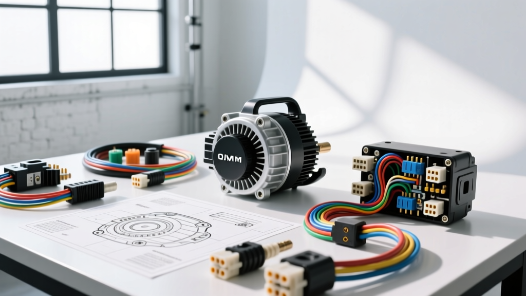
Evaluating High-Output Auto Electrical Components
When upgrading a vehicle’s electrical architecture for towing, off-road lighting, or RV applications, selecting the right charging and cranking components is critical. Specialized rebuilders and distributors, such as C & S Auto Electric Inc, have built a reputation for providing heavy-duty, custom-wound alternators and high-torque starters that outperform standard mass-market replacements. This product comparison and selection guide breaks down the technical differences between standard OEM units and premium rebuilt alternatives, providing the exact wiring specifications, AWG requirements, and diagnostic procedures needed for a flawless high-amp installation.
OEM vs. Premium Rebuilt: The Internal Architecture
Standard OEM alternators are engineered for baseline vehicle loads—typically 100A to 130A. They utilize standard epoxy-potted rectifier assemblies and round-wire stators. While adequate for stock vehicles, these components often suffer from thermal runaway when subjected to continuous high-draw scenarios like running a 2000W inverter or multiple LED light bars.
Conversely, high-output units sourced through specialized channels like C & S Auto Electric Inc feature distinct internal upgrades:
- Hairpin Stator Windings: Increases copper density in the stator slots, improving low-RPM output and overall thermal efficiency.
- Avalanche Diode Rectifiers: Capable of withstanding massive voltage spikes (load dumps) without failing, a common failure point in standard OEM rectifiers.
- Heavy-Duty Bearings: Upgraded to sealed, high-temperature synthetic greased bearings to handle the increased lateral belt tension required by high-amp pulleys.
Alternator Selection Matrix: Amperage vs. Application
Selecting the correct alternator output requires matching the amperage to your calculated continuous and peak electrical loads. Below is the selection matrix used by professional auto electricians to size alternators, main power cables, and overcurrent protection.
| Alternator Output | Target Application | BAT+ Wire Gauge (AWG) | Main Fuse (ANL/Mega) | Sense Wire Fuse |
|---|---|---|---|---|
| 130A - 150A | Stock replacement, minor audio upgrades | 6 AWG | 175A | 5A Inline |
| 180A - 220A | Heavy towing, winches, moderate inverters | 4 AWG | 250A | 5A Inline |
| 250A - 320A | RV house banks, extreme off-road, competition audio | 1/0 AWG | 350A | 10A Inline |
Note: Wire sizing assumes a maximum cable run of 4 feet from the alternator BAT+ terminal to the primary battery positive post. For longer runs, increase wire diameter by one AWG step to mitigate voltage drop, in accordance with SAE J1127 battery cable standards.
Wiring Harness Upgrades for 200A+ Alternators
Installing a 220A alternator on a factory wiring harness is a guaranteed way to melt the factory BAT+ wire and potentially cause an electrical fire. A complete front-end wiring upgrade is mandatory.
1. The Main Charge Cable (BAT+)
Remove the factory 8 AWG or 10 AWG charge wire. Install a new 4 AWG or 2 AWG stranded copper cable with a heavy-duty ring terminal (3/8" or 5/16" stud size, depending on the alternator post). Crimp using a hex-crimper to ensure a gas-tight connection, and seal with adhesive-lined heat shrink. Route the cable away from exhaust manifolds and steering shafts.
2. Upgrading the Voltage Regulator Connector
Many high-output units utilize the ubiquitous GM CS130D / CS144 4-pin regulator connector. When wiring this plug for a custom harness or standalone application, the pinout must be exact to ensure the internal regulator excites properly and senses true battery voltage.
- Pin P (Parallels): Often left unconnected in standalone swaps, or wired to a tachometer signal.
- Pin F (Field): PWM signal input from the PCM. In standalone swaps, this is typically left open or tied to a 12V switched source via a resistor.
- Pin L (Lamp/Excite): Must receive 12V+ from an ignition-switched source. Wire this through a 56-ohm resistor or a standard 194 incandescent bulb to prevent backfeeding and regulator damage.
- Pin S (Sense): The most critical pin. This must be wired directly to the battery positive terminal, fused at 5A within 6 inches of the battery. If wired to the alternator BAT+ post, the regulator will read alternator output voltage, not battery voltage, resulting in chronic undercharging.
3. Alternator Case Grounding
High-amp alternators push significant current through the chassis ground path. Relying on the mounting brackets is insufficient due to paint, corrosion, and galvanic reactions. Install a dedicated 2 AWG ground strap directly from the alternator mounting ear to a clean, bare-metal point on the engine block. Torque the mounting bolts to manufacturer specifications (typically 18-25 lb-ft for M8 bolts) to ensure mechanical stability without cracking the aluminum casing.
Starter Motor Selection: PMGR vs. Direct Drive
When sourcing starters through C & S Auto Electric Inc or similar premium suppliers, you will encounter Permanent Magnet Gear Reduction (PMGR) units versus older Direct Drive (DD) models. For any modified vehicle, PMGR is the mandatory choice.
PMGR starters utilize a planetary gear set that multiplies torque while allowing the use of a smaller, lighter, and faster-spinning electric motor. A standard 1.4 kW DD starter might draw 250 amps and struggle to turn over a high-compression engine. A premium 2.0 kW PMGR starter will draw fewer amps (approx. 180A) while delivering 30% more cranking torque to the flywheel. When installing a PMGR starter, ensure the starter solenoid trigger wire (typically 12 AWG) is upgraded if voltage drop at the solenoid exceeds 0.5V during cranking.
Real-World Troubleshooting: Voltage Drop Testing
After installing your upgraded alternator and heavy-gauge wiring, you must validate the circuit integrity using a digital multimeter (DMM). Do not rely solely on a dashboard voltmeter. Perform these tests with the engine running at 1500 RPM and a simulated load (headlights on high, HVAC blower on max).
Positive Side Voltage Drop Test
- Set DMM to DC Volts.
- Place the red probe directly on the alternator BAT+ terminal (the metal nut, not the wire).
- Place the black probe directly on the battery positive post (the lead post, not the clamp).
- Specification: The reading must be less than 0.200V (200mV). If it reads 0.450V or higher, you have a poor crimp, an undersized wire, or a corroded fuse connection.
Negative Side Voltage Drop Test
- Place the red probe on the alternator metal casing.
- Place the black probe on the battery negative post.
- Specification: The reading must be less than 0.100V (100mV). Higher readings indicate a failing engine-to-chassis ground strap or corroded battery terminals.
Final Integration and System Validation
Upgrading to high-output electrical components requires a holistic approach to the vehicle's wiring architecture. By utilizing premium rebuilt units and adhering to strict AWG sizing, proper pinout configurations, and rigorous voltage drop testing, you ensure a reliable electrical system capable of handling extreme auxiliary loads. Always refer to Eaton Bussmann circuit protection guidelines when selecting ANL or Mega fuses to ensure your overcurrent protection matches the interrupt rating required by high-capacity lithium or AGM battery banks.