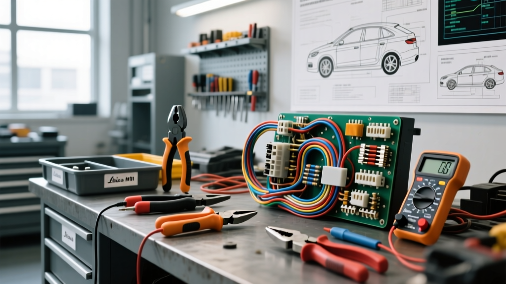
Benchmarking Professional Auto Electrical Diagnostics
When benchmarking a professional automotive electrical facility against the operational standards of a premier Harris Auto Electric shop, the investment in precision diagnostic and fabrication tooling is substantial but non-negotiable. Modern vehicle architecture relies heavily on multiplexed CAN/LIN networks, high-amperage 48V mild-hybrid systems, and complex alternator voltage regulators. To accurately diagnose parasitic draws, decode serial data buses, and fabricate reliable harnesses, an auto electrician must equip their bench with industry-grade oscilloscopes, pneumatic crimping infrastructure, and SAE-compliant wiring materials.
This cost and tool requirements analysis breaks down the essential capital expenditure (CapEx) required to build a top-tier auto electrical diagnostic station, focusing on wire termination, high-current load testing, and network analysis.
Core Diagnostic Equipment & Oscilloscope Costs
The foundation of any advanced electrical diagnostic bay is a high-bandwidth automotive oscilloscope and a true-RMS digital multimeter (DMM). While basic code readers can identify a missing CAN bus signal, they cannot reveal why the signal is dropping out.
Oscilloscope and Probe Investment
A professional setup requires a minimum 4-channel oscilloscope with at least 20 MHz bandwidth and a 200 MS/s sampling rate to accurately capture fast-acting PWM (Pulse Width Modulation) signals, such as those controlling modern fuel injectors or electronic throttle bodies. The PicoScope 4425A Advanced Diagnostics Kit is the industry standard, retailing at approximately $1,399. This kit includes essential 60A and 20A current clamps, which are mandatory for non-intrusive parasitic draw testing and starter motor amperage profiling.
Additionally, you must budget for 10:1 and 20:1 attenuators (approx. $45 each) to safely measure high-voltage ignition coil primary circuits and piezoelectric injector signals without damaging the scope's internal circuitry.
True-RMS Multimeters and Breakout Boxes
For voltage drop testing across starter circuits and main power distribution fuse boxes, a True-RMS automotive DMM with Min/Max recording is required. The Fluke 88V Automotive Multimeter (approx. $425) is preferred for its ability to capture intermittent microsecond voltage spikes and its built-in RPM and duty cycle functions. Pair this with a comprehensive OBD-II breakout box ($85) to safely back-probe the 16-pin DLC (Data Link Connector) without piercing wire insulation, which introduces corrosion risks.
Terminal Crimping Infrastructure: Deutsch, Molex, and TE
Operating at the level of a Harris Auto Electric facility means abandoning solder-and-heat-shrink repairs on under-hood harnesses. Solder creates rigid stress points that fracture under engine vibration. Instead, professional shops utilize gas-tight, cold-weld crimp terminations adhering to TE Connectivity and IPC/WHMA-A-620 standards.
Setting up a professional crimping station requires investing in precision ratcheting hand tools or pneumatic crimp presses, alongside a vast inventory of sealed connectors.
Connector and Tooling Cost Matrix
| Connector System | Wire Gauge (AWG) | Recommended Crimp Tool | Die Setting / Color | Est. Tool Cost |
|---|---|---|---|---|
| Deutsch DT (Sealed) | 16 - 20 AWG | TE 58548-1 or DMC AF8 | Yellow / 4-6 | $450 - $750 |
| Deutsch DTP (High Amp) | 10 - 14 AWG | TE 58548-1 (w/ DTP die) | Green / 2-4 | $450 + $180 (Die) |
| Molex MX150 (Unsealed/ECU) | 14 - 22 AWG | Molex 63811-8000 | Auto-Stop Ratchet | $385 |
| AMP Superseal 1.5 | 16 - 20 AWG | TE 58548-1 | Red / 5-7 | $450 |
| Weather-Pack (Legacy GM) | 14 - 18 AWG | Delphi/Packard Hand Crimper | Standard Jaw | $120 |
Crimp Quality Inspection and Wire Preparation
To achieve a gas-tight crimp, wire preparation is critical. When working with SAE J1128 GXL (Cross-linked polyethylene) wire, the insulation must be stripped exactly to the terminal's wire barrel depth—typically 3.5mm for 18 AWG solid Deutsch pins. The crimp must exhibit a proper 'bellmouth' (0.25mm to 0.75mm of exposed wire strands at the front of the wire barrel) to prevent the sharp edge of the terminal from shearing the copper strands during vibration. Budget an additional $250 for a digital terminal pull-force tester to validate crimp integrity on custom harness builds.
Building a High-Amperage 12V/24V Load Test Bench
A dedicated electrical test bench is required to rebuild and verify high-output alternators (up to 350A) and OEM starter motors. The wiring infrastructure of the bench itself must handle extreme thermal and electrical loads without inducing artificial voltage drops.
Wire Sizing and Busbar Architecture
For the main B+ (Battery Positive) and B- (Ground) busbars, you must use 2/0 AWG (70mm²) fine-strand, pure copper welding cable with an EPDM rubber jacket. Standard PVC battery cable will melt under sustained 250A alternator load testing. Connect the busbars using 3/8-inch copper ring terminals, crimped with a 12-ton hydraulic press. The torque specification for a 3/8-inch steel busbar bolt is 18-22 ft-lbs; failing to torque these connections will result in a high-resistance joint, generating excessive heat and skewing your alternator output readings.
For the control circuits on the bench, use 10 AWG GXL (Red) for the ignition sense circuit and 14 AWG GXL (Yellow) for the LIN (Local Interconnect Network) bus communication line that interfaces with modern Bosch and Denso alternator voltage regulators. LIN bus signals typically operate at 12V peak and 19.2 kbps, requiring a clean, unshielded twisted pair routed away from the high-amperage B+ cables to prevent electromagnetic interference (EMI).
Parasitic Draw and CAN Bus Diagnostic Tooling
Modern vehicles feature dozens of modules that remain awake long after the ignition is turned off. Diagnosing a parasitic draw on a late-model BMW or Land Rover requires patience and specialized current measurement tools.
Current Shunts and Sleep Mode Analysis
A standard multimeter fused at 10A will blow instantly if a module wakes up during a sleep-cycle test. Instead, professional auto electricians use a low-amp current clamp (e.g., PicoScope TA018, approx. $275) paired with a parallel resistor shunt setup. This allows you to leave the oscilloscope recording for up to 45 minutes while the vehicle's CAN bus goes to sleep. You must monitor the OBD-II DLC pins: Pin 6 (CAN-H, typically White or Yellow) and Pin 14 (CAN-L, typically Blue or Green). A healthy sleeping CAN bus will show 0V differential, and the quiescent current draw should drop below 30mA (0.03A). If a module keeps the network alive, you will see the CAN-H line pulsing to 2.5V-3.5V and CAN-L dropping to 1.5V-2.5V on the scope trace, allowing you to isolate the faulty node without pulling fuses and waking the network back up.
ROI Analysis: When Do the Tools Pay Off?
The initial CapEx for a Harris Auto Electric-grade tooling setup—including the PicoScope, TE crimping infrastructure, hydraulic presses, and SAE-compliant wire inventory—easily exceeds $4,500. However, the return on investment is realized through drastic reductions in diagnostic time and warranty comebacks.
By utilizing an oscilloscope to perform relative compression tests via the starter motor current waveform, a technician can identify a burnt exhaust valve or weak cylinder in 15 minutes, bypassing hours of manual teardown. Similarly, utilizing proper Deutsch and Molex crimping tools eliminates the 'ghost' electrical faults caused by corroded solder joints and high-resistance splices. In the professional automotive electrical sector, precision tooling is not an overhead expense; it is the primary mechanism for ensuring diagnostic accuracy and long-term harness reliability.