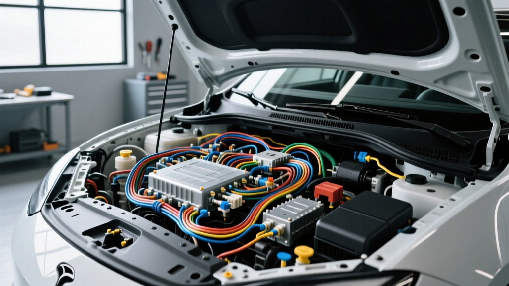
Advanced Electrical Diagnostics: Regional Standards & Environmental Factors
Modern vehicle electrical architecture requires a systematic, data-driven approach to troubleshooting. When benchmarking against a top-rated Lawrenceville auto electric Lawrenceville GA facility, master technicians emphasize that regional environmental factors—specifically the high ambient summer humidity and thermal cycling in Gwinnett County—accelerate galvanic corrosion in unsealed connectors and increase parasitic draw anomalies. To replicate the diagnostic success of elite Southeast repair shops, technicians must abandon guesswork and adopt rigorous step-by-step electrical troubleshooting flows.
This guide details advanced diagnostic decision trees for three of the most common and complex electrical failures: parasitic battery drains, Controller Area Network (CAN) bus communication faults, and high-current starter circuit voltage drops. By utilizing precise digital multimeter (DMM) measurements, oscilloscope bias checks, and OEM wiring schematics, you can isolate faults without inducing secondary module failures.
Flow 1: Parasitic Draw Isolation (The mV Drop Method)
Historically, technicians diagnosed parasitic draws by disconnecting the negative battery terminal and placing an ammeter in series. On modern vehicles with complex CAN networks, this is a critical error. Breaking the circuit resets module sleep timers, forcing the vehicle to remain awake and yielding false-high current readings. Furthermore, pulling the battery cable can trigger anti-theft lockouts and erase volatile memory in the ECM and TCM.
Elite diagnosticians use the Voltage Drop (mV) Method across the vehicle's fuse panel. Every fuse acts as a low-value shunt resistor. By measuring the millivolt (mV) drop across the test points on the top of ATO and Mini fuses, you can calculate the exact current flow without breaking the circuit.
Decision Tree: Parasitic Draw > 50mA
- Step 1: Connect a DMM set to DC millivolts (mV). Ensure the vehicle is locked, hood latch is manually depressed (to simulate a closed hood), and key fob is placed in a Faraday bag at least 15 feet away to prevent passive RFID wake-ups.
- Step 2: Wait 20–40 minutes for all modules to enter CAN sleep mode. Target sleep current is typically 20mA to 50mA.
- Step 3: Probe the exposed metal test points on the top of each fuse in the interior and under-hood fuse boxes.
- Step 4: If a fuse reads >0.5mV, consult the Fuse Voltage Drop Matrix below to determine if the circuit exceeds the 50mA threshold.
- Step 5: Once the offending circuit is identified, pull the fuse. If the draw drops, trace the wiring harness for chafed insulation, wet connector cavities, or failing aftermarket accessories (e.g., dashcams hardwired to constant B+).
Technical Reference: Mini/ATO Fuse Voltage Drop Matrix
The following table correlates millivolt drop to current draw based on standard cold-resistance values of OEM blade fuses. Note that resistance decreases as the fuse element heats up under load; these baseline values are for identifying low-amperage parasitic sleep draws.
| Fuse Rating | Typical Cold Resistance | mV Drop at 10mA (Sleep) | mV Drop at 50mA (Max Sleep) | mV Drop at Max Load |
|---|---|---|---|---|
| 10A Mini | ~7.5 mΩ | 0.075 mV | 0.37 mV | ~75 mV |
| 15A Mini | ~5.0 mΩ | 0.050 mV | 0.25 mV | ~75 mV |
| 20A ATO | ~3.5 mΩ | 0.035 mV | 0.17 mV | ~70 mV |
| 30A ATO | ~2.2 mΩ | 0.022 mV | 0.11 mV | ~66 mV |
Source: Reference data aligned with SAE J1292 Automobile Electrical Systems standards for overcurrent protection.
Flow 2: CAN Bus Communication Faults (U-Codes)
A generic U0100 code (Lost Communication with ECM/PCM) is often misdiagnosed as a failed computer. In reality, 90% of U-codes are caused by physical layer faults in the CAN wiring harness. The High-Speed CAN network (ISO 11898-2) operates on a differential voltage signal. When diagnosing a total network collapse, technicians must verify the terminating resistors and bias voltages at the Data Link Connector (DLC).
Diagnostic Path: U0100 Network Isolation
- Step 1: DLC Pinout Verification. Locate the OBD-II DLC (usually under the driver dash). Identify Pin 6 (CAN-High)Pin 14 (CAN-Low)
- Step 2: Resistance Check (Key OFF). Set DMM to Ohms. Measure across DLC Pin 6 and Pin 14.
- 60 Ω: Network is physically intact (two 120Ω terminating resistors in parallel).
- 120 Ω: One terminating resistor is missing or a module containing a resistor is offline/disconnected.
- < 60 Ω: Short to ground, short between CAN-H and CAN-L, or an aftermarket device injecting parallel resistance.
- Step 3: Bias Voltage Check (Key ON, Engine OFF). Set DMM to DC Volts. Measure Pin 6 to chassis ground (should read ~2.6V). Measure Pin 14 to chassis ground (should read ~2.4V). If both read 0V, the CAN transceiver in the ECM has lost power or ground. If both read 12V, the CAN-H line is shorted to battery positive.
- Step 4: Oscilloscope Validation. For intermittent faults caused by micro-corrosion in humid environments, a DMM is too slow. Connect a dual-channel scope to Pins 6 and 14. Verify that the CAN-H and CAN-L waveforms are perfect mirror images of each other, peaking at 3.5V and 1.5V respectively during dominant bit transmission.
CAN Bus Specification Chart
| Parameter | CAN-High (DLC Pin 6) | CAN-Low (DLC Pin 14) |
|---|---|---|
| Recessive State (Rest) | ~2.5V to 2.6V | ~2.4V to 2.5V |
| Dominant State (Active) | ~3.5V | ~1.5V |
| Terminating Resistor | 120 Ω (to CAN-L) | 120 Ω (to CAN-H) |
| Twisted Pair Spec | Minimum 1 twist per inch to reject EMI/RFI interference | |
For deeper network topology insights, refer to the ASE L1 Advanced Engine Performance & Electrical Certification testing guidelines.
Flow 3: High-Current Starter Circuit Voltage Drop
When a vehicle exhibits slow cranking, the immediate assumption is often a weak battery or a failing starter motor. However, a failing positive battery cable or a corroded engine ground strap is equally likely. A starter motor can draw 150A to 250A during cranking. According to Ohm's Law (V = I × R), even 0.05 Ω of unwanted resistance in a 1/0 AWG cable will result in a massive voltage drop, robbing the starter of torque.
Step-by-Step Cranking Voltage Drop Test
- Preparation: Ensure the battery is fully charged and passes a conductance test (minimum 80% of rated CCA). Disable the ignition system or fuel injectors to prevent the engine from starting during the test.
- Positive Side Test: Connect the DMM red lead to the battery positive post (NOT the terminal clamp) and the black lead to the starter B+ terminal stud. Crank the engine. The reading must be less than 0.5V for the entire positive cable run. If it reads higher, inspect the 1/0 AWG cable for internal green-copper corrosion, common in coastal or high-humidity regions.
- Negative Side Test: Connect the DMM red lead to the starter motor casing (bare metal) and the black lead to the battery negative post. Crank the engine. The reading must be less than 0.2V.
- Connection Drop Test: If the overall cable drop is high, test across individual connections (e.g., from the battery post to the clamp, from the fuse box stud to the cable lug). Each mechanical connection should exhibit a voltage drop of less than 0.1V.
Terminal Repair & Torque Specifications
When repairing high-current circuits, never use solder. Solder has a lower melting point and higher resistance than copper, and it will flow under high mechanical stress, causing a loose connection. Instead, use an OEM-spec open-barrel crimper for unsealed terminals or a Deutsch DT/Weather-Pack crimping die for sealed connectors. For the starter B+ terminal, ensure the M10 flange nut is torqued to 12–15 Nm (89–132 lb-in) to prevent micro-arcing under heavy cranking loads.
Summary of Best Practices
Mastering automotive electrical diagnostics requires moving beyond basic code reading and embracing the physics of the circuit. Whether you are tracking down a 30mA parasitic draw using the mV drop method, verifying 60-ohm CAN bus terminating resistors, or measuring starter circuit voltage drops under a 200A load, precision is paramount. Technicians who adopt these rigorous, step-by-step troubleshooting flows will drastically reduce diagnostic time, eliminate unnecessary parts replacement, and deliver the high-level expertise expected of premier auto electric specialists.
For comprehensive wiring schematics and connector pinout databases, always consult OEM service information via Motor AllData or equivalent factory portals before piercing wires or back-probing delicate ECM terminals.