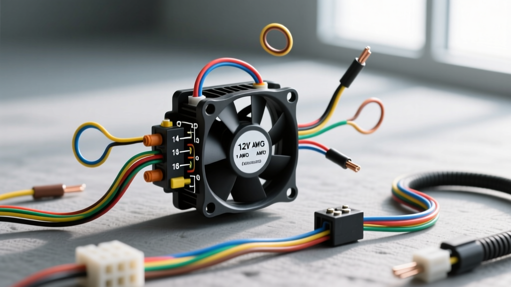
Introduction to Electric Cooling Fan Circuits
Transitioning from a mechanical clutch fan to an electric cooling fan is one of the most effective ways to free up parasitic horsepower, reduce engine noise, and improve low-speed cooling efficiency. However, the success of this upgrade relies entirely on a properly executed auto electric fan wiring diagram. Electric fans are high-amperage devices; a standard 16-inch single fan can draw between 15 and 25 amps continuously, with startup inrush currents peaking over 40 amps.
For beginners, wiring a high-draw component directly to a dashboard switch or a basic thermostatic sensor is a recipe for melted harnesses, voltage drops, and electrical fires. This guide breaks down the fundamental relay logic, wire gauge requirements, and circuit routing necessary to build a safe, reliable, and OEM-grade cooling fan circuit.
Decoding the Standard 4-Pin ISO Relay
The heart of any robust auto electric fan wiring diagram is the automotive relay. A relay acts as a heavy-duty, electrically operated switch. It allows a low-amperage control circuit (like a thermostat switch or ECU signal) to safely trigger a high-amperage load circuit (the fan motor) without routing heavy-gauge wires through the firewall or dashboard.
Most universal fan kits and OEM applications utilize a standard ISO Mini 4-Pin Relay. Understanding the pinout is critical for proper circuit design:
- Pin 30 (Common / Input): Connected to the battery positive via a primary fuse. This is the high-amperage power source.
- Pin 87 (Normally Open / Output): Connected to the positive terminal of the electric fan motor. Power flows from Pin 30 to Pin 87 only when the relay is energized.
- Pin 86 (Coil Positive): The trigger wire. Connected to a 12V switched ignition source, a thermostatic switch, or the ECU fan control module.
- Pin 85 (Coil Negative): Connected to a clean chassis or engine block ground. This completes the low-amp electromagnetic coil circuit.
When 12V is applied to Pin 86 and Pin 85 is grounded, the internal electromagnet energizes, pulling the contact bridge down to connect Pin 30 to Pin 87, thereby sending battery voltage to the fan.
Wire Gauge (AWG) and Color Coding Standards
Selecting the correct American Wire Gauge (AWG) is non-negotiable. According to the SAE J1128 Low Tension Primary Cable standard, wire sizing must account for the total circuit length (positive and negative runs combined) and the maximum continuous amperage, factoring in the high under-hood ambient temperatures.
Below is the recommended wire sizing chart for standard 12V electric cooling fans:
| Fan Amp Draw (Continuous) | Total Wire Run Length | Minimum Load Circuit AWG | Control Circuit AWG |
|---|---|---|---|
| Up to 15 Amps | Under 10 Feet | 12 AWG | 16 AWG |
| 15 - 25 Amps | Under 10 Feet | 10 AWG | 16 AWG |
| 25 - 35 Amps (Dual Fans) | Under 10 Feet | 8 AWG | 14 AWG |
| Over 35 Amps | Over 10 Feet | 6 AWG | 14 AWG |
Note: Always use stranded copper wire rated for automotive use (GXL or TXL cross-linked polyethylene insulation), never solid copper household wire, which will fracture under engine vibration.
Standard DC Automotive Color Codes
While aftermarket kits vary, adhering to standard SAE color conventions makes future troubleshooting significantly easier:
- Red: Constant 12V Battery Power (Load Circuit)
- Black: Main Chassis/Engine Ground
- Blue or Yellow: Switched 12V Trigger / Thermostat Signal (Control Circuit)
- Green or White: Relay Output to Accessory (Load Circuit)
Step-by-Step Wiring Execution
Follow this sequence to wire a single electric fan using a standard 4-pin relay, a 30A inline fuse, and a thermostatic probe switch.
- Route the Main Power: Run a 10 AWG red wire from the positive battery terminal to an inline 30A (or 40A time-delay) fuse holder, mounted within 18 inches of the battery. Continue this wire to Relay Pin 30.
- Wire the Load Output: Run a 10 AWG wire from Relay Pin 87 to the positive terminal on the fan motor. Use a Weather-Pack or Metri-Pack 280 sealed connector to prevent moisture intrusion.
- Establish the Motor Ground: Run a 10 AWG black wire from the fan motor's negative terminal directly to the engine block or a dedicated chassis ground stud. Never ground the fan to the radiator support or aluminum radiator tabs.
- Wire the Control Trigger: Run an 18 AWG wire from a 12V ignition-switched source (so the fan cannot run after the key is off) to the 'Input' side of your thermostatic probe switch. Run another 18 AWG wire from the 'Output' side of the switch to Relay Pin 86.
- Ground the Relay Coil: Run an 18 AWG black wire from Relay Pin 85 to a clean, bare-metal chassis ground.
Integrating ECU Triggers and Flyback Diodes
Modern engine swaps (like LS or Coyote V8s) often use the ECU to control fan relays based on precise coolant temperature tables. When wiring an auto electric fan diagram to an ECU output, you must consider inductive kickback.
When the relay coil de-energizes, the collapsing magnetic field generates a high-voltage spike in the opposite direction. If the ECU driver transistor absorbs this spike, it can fry the ECU's internal circuitry. To prevent this, use a 5-pin relay with an internal suppression resistor, or wire a flyback diode (like a 1N4007) across Pins 85 and 86, with the diode's stripe facing Pin 86. Alternatively, many modern Littelfuse automotive relays come with built-in diodes specifically for ECU-safe switching.
Common Beginner Mistakes and Troubleshooting
Even with a correct schematic, physical execution errors cause 90% of cooling fan failures. Use this diagnostic tree to troubleshoot common issues:
Symptom: Fan Runs Backward (Pushing Air Away from Radiator)
- Cause: Reversed polarity on the DC motor.
- Fix: DC motors are not polarity-sensitive regarding operation, only direction. Swap the positive and negative wires at the fan motor connector. Verify airflow direction before finalizing the harness.
Symptom: Relay Clicks, but Fan Hums Weakly or Doesn't Spin
- Cause: Severe voltage drop on the load circuit or a poor ground.
- Fix: Use a digital multimeter to measure voltage directly at the fan connector while the relay is engaged. If you read 10.5V instead of 12.4V+, you have undersized wires or corroded crimps. Upgrade to 8 AWG wire and solder/shrink all connections. Clean the engine block ground point with a wire brush.
Symptom: Inline Fuse Blows Instantly Upon Startup
- Cause: Inrush current spike exceeding the fuse rating.
- Fix: Electric motors draw 2x to 3x their running amperage for the first 500 milliseconds to overcome inertia. Replace standard fast-blow fuses with Time-Delay (Slow-Blow) fuses rated for 125% of the fan's continuous running amp draw.
Summary of Best Practices
A reliable auto electric fan wiring diagram is only as good as its physical components. Always use ratcheting crimpers for uninsulated terminals, apply adhesive-lined marine-grade heat shrink to all connections, and secure the harness away from exhaust manifolds and moving pulleys. By respecting relay logic, adhering to SAE wire gauge standards, and ensuring pristine ground connections, your electric cooling system will provide years of reliable, worry-free operation.