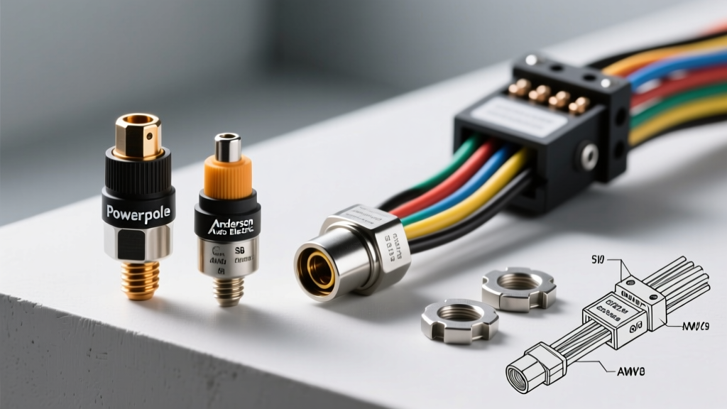
The Evolution of High-Current Auto Electric Interconnects
Modern vehicle electrical architectures demand far more than the factory alternator and starter circuits were originally designed to handle. From 12,000-lb winches and dual-battery isolation systems to EV conversions and high-output solar arrays, the backbone of any reliable build lies in its high-current interconnects. When building out an advanced Anderson auto electric system, technicians and overlanders consistently face a critical selection dilemma: Which connector topology offers the best balance of current capacity, vibration resistance, and serviceability?
This guide provides an expert-level comparison of Anderson Power Products (APP) connector families—specifically the Powerpole and SB (Storage Battery) series—against traditional automotive ring terminals and sealed Deutsch connectors. We will break down AWG mapping, crimping methodologies, and real-world failure modes to help you engineer a bulletproof electrical distribution network.
Connector Comparison Matrix: High-Current Auto Applications
Before selecting a connector, it is vital to understand the mechanical and electrical limitations of each topology under hood-level heat and chassis vibration. Below is a technical comparison of the most common high-amperage connection methods.
| Connector Type | Max Continuous Amps | Environmental Seal | Vibration Resistance | Primary Auto Application |
|---|---|---|---|---|
| Anderson Powerpole (APP) | 15A - 45A | Unsealed (IP20) | High (Flat-wiping contacts) | Radio comms, lighting, auxiliary fuse blocks |
| Anderson SB Series (SB50/SB175) | 50A - 350A | Unsealed (IP20) | Very High (Spring-loaded) | Dual battery links, winch quick-disconnects |
| Deutsch DTP Series | 25A (per pin) | Fully Sealed (IP68) | High (Silicone seals) | Under-hood sensors, sealed lighting harnesses |
| Traditional Ring Terminal (Lug) | Depends on stud size | Unsealed | Low (Prone to backing off) | Alternator B+ posts, starter solenoids |
Deep Dive: Anderson Powerpole (APP) Series
The Anderson Powerpole series is the gold standard for low-to-medium current (up to 45A) modular distribution in auto electric setups. Unlike traditional Molex or weather-pack connectors, APPs utilize a genderless housing design and a flat-wiping, silver-plated copper contact system.
AWG Wire Mapping and Housing Color Codes
Selecting the correct housing and contact is critical. Using a 15A contact on a 10 AWG wire will result in catastrophic thermal failure. Always match the wire gauge to the specific Anderson contact stamping.
- 15A / 30A Housings (Red/Black/Blue/Yellow): Accepts 20 AWG to 12 AWG wire. Ideal for auxiliary lighting relays, ham radio power taps, and fridge slide circuits.
- 45A Housings (Gray): Accepts 14 AWG to 10 AWG wire. Used for high-draw DC-DC chargers and small inverter feeds.
- 120A Housings (Blue): Accepts 6 AWG to 2 AWG wire. Heavy-duty distribution blocks.
Expert Tip: The color of the Powerpole housing does not dictate the amperage; the physical size of the housing does. However, standardizing your build (e.g., Gray for 45A, Red for 30A) prevents accidental mating of mismatched circuits.
Heavy-Duty Auto Electric: The Anderson SB (Storage Battery) Series
When your auto electric system requires 50 amps or more, the Powerpole series is insufficient. The Anderson SB series relies on a rugged polycarbonate housing and a stainless steel leaf spring that maintains constant forward pressure on the contacts, preventing fretting corrosion caused by engine harmonics and chassis flex.
SB50 vs. SB175: Specifications and Torque
The SB50 is the workhorse of the 12V overlanding and marine world, while the SB175 is reserved for extreme loads like EV battery banks and heavy winching.
| Specification | Anderson SB50 | Anderson SB175 |
|---|---|---|
| Max Continuous Current | 50A (with 6 AWG) | 175A (with 1/0 AWG) |
| Wire Range | 20 AWG to 6 AWG | 6 AWG to 1/0 AWG |
| Terminal Thread | #10-32 UNC | 1/4-20 UNC |
| Terminal Torque Spec | 20 in-lbs | 60-70 in-lbs |
| Typical Housing Color | Gray (Standard), Red, Blue | Red (Standard), Gray |
According to SAE J1123 standards for high-current connectors, maintaining proper torque on mechanical bus-bar terminals (like those found on the SB175) is vital to prevent micro-arcing and localized resistance heating.
Step-by-Step: Crimping Anderson Powerpoles for Automotive Use
The most common point of failure in an Anderson auto electric harness is an improper crimp. Soldering Anderson contacts is strictly prohibited by the manufacturer; the heat from the solder wicks into the contact spring, ruining the temper and causing loss of contact pressure. You must use a proper ratcheting crimp tool.
- Strip the Wire: Strip exactly 5/16" for 12-16 AWG, and 1/2" for 10 AWG. Do not nick the copper strands.
- Select the Die: Use a flat-wire crimp die (not an indent or hex die). The Anderson Powerpole contact features a specific wire barrel designed to be crushed flat.
- Position the Contact: Insert the contact into the crimp tool with the wire barrel facing you and the mating tongue facing away. Ensure the tool locator rests in the center insulator ridge.
- Execute the Crimp: Squeeze the ratchet until it releases. The wire barrel should wrap tightly around the copper strands with no visible copper outside the barrel, and the insulation grip should securely hold the wire jacket.
- Insert into Housing: Push the crimped contact into the polycarbonate housing until you hear a distinct "click." The stainless steel retention spring will lock it in place.
Real-World Troubleshooting & Failure Modes
Even premium connectors fail if installed poorly or subjected to conditions beyond their IP rating. Use this decision tree to diagnose high-current Anderson connector issues:
Symptom: Connector Housing is Melting or Discolored
- Cause 1: Undersized wire for the load. (e.g., pulling 40A through a 30A Powerpole on 14 AWG wire).
- Cause 2: Poor crimp causing high resistance at the wire-to-terminal junction.
- Fix: Perform a millivolt drop test. Place your multimeter probes on either side of the connector while under load. A voltage drop greater than 0.05V indicates excessive resistance. Re-crimp using the correct AWG and flat-die tool.
Symptom: Intermittent Power Loss Over Bumps
- Cause 1: Fretting corrosion on the contacts due to lack of spring pressure (common if contacts were soldered instead of crimped).
- Cause 2: Housing not fully seated, or retention spring bypassed.
- Fix: Disassemble the connector. Inspect the silver plating on the flat-wiping surface. If black oxidation is present, clean with contact cleaner and a fiberglass scratch pen. Apply a thin layer of dielectric grease to the mating surfaces to prevent future oxidation, as recommended by Expedition Portal 12V wiring guidelines.
Symptom: SB50 Connector Won't Mate Fully
- Cause: Attempting to mate an SB50 to an SB120 or SB175, or using mismatched keying configurations. Anderson uses physical plastic keys and color-coding to prevent cross-mating different voltage systems (e.g., 12V vs 24V vs 48V).
- Fix: Verify housing color and physical keying slots. Standard 12V auto systems should universally use Gray SB50s to ensure interoperability with recovery gear and trailer feeds.
Expert Verdict: When to Use Anderson vs. Alternatives
For sealed under-hood environments where water and oil intrusion are guaranteed (e.g., near the firewall or radiator support), you must use sealed alternatives like the Deutsch DTP or Amphenol SurLok series. Anderson connectors are unsealed and will suffer galvanic corrosion if exposed to continuous moisture.
However, for chassis-mounted distribution blocks, dual-battery quick-disconnects, and interior auxiliary panels, the Anderson auto electric ecosystem is unmatched. The SB175 provides a safe, hot-pluggable, high-amperage link that traditional ring terminals simply cannot offer without the risk of vibration-induced loosening. By strictly adhering to AWG mappings, utilizing proper ratcheting crimp tools, and implementing millivolt-drop testing during commissioning, you will build a vehicle electrical system capable of handling extreme expedition demands for decades.
For further technical datasheets on contact plating and derating curves at elevated ambient temperatures, refer directly to the Anderson Power Products Vehicle Interconnects documentation.