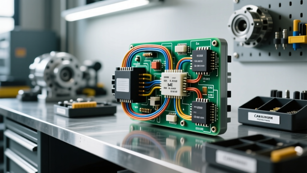
Midwest Climate Realities: Why Auto Electrical Standards Matter
When diagnosing parasitic draws, melted harnesses, or erratic module behavior in extreme Midwest climates, technicians at a specialized auto electric Lawrence KS facility know that thermal cycling is the ultimate enemy of automotive wiring. Kansas seasons swing from -10°F winters to 105°F summers, causing wire insulation to become brittle and galvanic corrosion to accelerate at chassis ground points. What might pass as a "quick fix" in a mild coastal climate will rapidly fail in the Midwest, leading to catastrophic electrical fires or destroyed control modules.
This guide outlines the most critical safety warnings and fatal wiring mistakes encountered in general automotive electrical repair, backed by SAE standards and professional diagnostic protocols.
Critical Safety Warnings: Before You Strip a Wire
Automotive electrical systems are no longer simple 12-volt analog circuits. Modern vehicles utilize high-amperage feeds, sensitive multiplexed data networks, and explosive pyrotechnic devices. Ignore these safety protocols at your own peril.
1. The SRS (Airbag) Capacitor Discharge Protocol
The Supplemental Restraint System (SRS) operates on a dedicated backup power supply. Even with the battery disconnected, the SRS diagnostic module retains enough capacitive charge to deploy an airbag or seatbelt pretensioner. Always disconnect the negative battery terminal and wait a minimum of 10 to 15 minutes before probing any yellow-jacketed Metripack 150 connectors. According to the NHTSA Air Bag Safety Guidelines, improper probing of SRS circuits with a standard multimeter can inadvertently trigger the pyrotechnic squib, causing severe injury.
2. High-Voltage EV/Hybrid Interlocks
If you are working near orange-jacketed high-voltage (HV) cabling on a hybrid or EV, standard 12V rules do not apply. These circuits carry between 200V and 800V DC. Never attempt to repair, splice, or probe orange HV cables. Always verify the service disconnect plug is removed and use a CAT III or CAT IV rated multimeter to verify 0V at the inverter terminals before touching any adjacent low-voltage harnesses.
The 4 Fatal Wiring Mistakes (And How Professionals Fix Them)
Mistake 1: The "Twist-and-Tape" Splice
The Error: Twisting two bare copper wires together and wrapping them in standard vinyl electrical tape.
The Consequence: Vinyl tape adhesive dries out and unrolls under under-hood heat. More importantly, the exposed copper strands act as a wick. Through capillary action, moisture and road salt will travel inches up the wire jacket, causing green copper oxide corrosion that creates high-resistance voltage drops deep inside the harness.
The Professional Fix: For under-hood or under-chassis repairs, never use a splice. Cut out the damaged section and install a Deutsch DT 2-pin or 3-pin connector with proper crimp tools and silicone wedge locks. If an inline splice is absolutely necessary in the cabin, use a solder-sleeve heat shrink or a copper crimp barrel sealed with dual-wall adhesive-lined heat shrink. The inner meltable adhesive layer creates a watertight environmental seal that blocks capillary wicking.
Mistake 2: Undersized AWG for High-Amperage Feeds
The Error: Using 14 AWG wire to feed a 40-amp relay for an aftermarket off-road light bar or fuel pump.
The Consequence: Wire gauge dictates ampacity and voltage drop. A 14 AWG wire pushing 40 amps will overheat, melting the insulation and potentially igniting nearby sound-deadening materials. Furthermore, the voltage drop will starve the accessory. A fuel pump receiving 10.5V instead of 13.8V will run slower, drop fuel pressure, and cause lean misfires under load.
The Professional Fix: Always size wire according to the SAE J1128 Low Tension Primary Cable Standard. Factor in the total length of the circuit (positive feed + ground return) to calculate voltage drop. For a 40A continuous draw over 10 feet, a minimum of 10 AWG (or ideally 8 AWG) primary automotive wire is required.
Mistake 3: Chassis Grounding to Painted or Dirty Metal
The Error: Securing a ground ring terminal to a painted chassis bracket using a standard self-tapping sheet metal screw.
The Consequence: Paint, powder coating, and rust are electrical insulators. The circuit will attempt to find an alternative path to ground, often back-feeding through sensitive ECU logic grounds, instantly frying a $1,500 control module.
The Professional Fix: Use a roto-file or sandpaper to strip the ground point down to bare, shiny steel. Use a proper M6 or M8 flange bolt with a star washer (internal or external tooth lock washer) to bite into the metal and prevent vibration loosening.
- M6 Bolt Torque Spec: 10 Nm (7.4 lb-ft)
- M8 Bolt Torque Spec: 20 Nm (14.7 lb-ft)
Mistake 4: Destroying CAN-Bus Twisted Pair Geometry
The Error: Untwisting CAN-High and CAN-Low wires to probe them with multimeter leads, or replacing a damaged section with untwisted, parallel wires.
The Consequence: The Controller Area Network (CAN) relies on differential signaling and electromagnetic interference (EMI) cancellation. The wires are twisted exactly 3 to 4 times per inch. Untwisting them exposes the network to alternator whine and ignition coil EMI, resulting in U-codes (e.g., U0100 Lost Communication with ECM) and erratic dashboard behavior.
The Professional Fix: When repairing a CAN bus, maintain the twist rate right up to the connector housing. On a standard J1962 OBD2 port, CAN-H is Pin 6 and CAN-L is Pin 14. If splicing is required, use shielded twisted-pair cable and ground the shield drain wire at one end only to prevent ground loops.
SAE J1128 Wire Gauge & Ampacity Reference Chart
The following chart outlines maximum continuous ampacity for single-circuit, under-hood automotive primary wire (rated for 125°C) based on SAE J1128 standards. Note that bundling multiple wires together in a conduit reduces heat dissipation and requires derating the ampacity by up to 20%.
| AWG Size | Cross-Section (mm²) | Max Amps (Single Wire) | Voltage Drop per 10ft @ Max Amps | Common Application |
|---|---|---|---|---|
| 18 AWG | 0.80 | 6A | 0.12V | Sensors, low-draw LEDs, ECU logic triggers |
| 16 AWG | 1.30 | 10A | 0.13V | Interior lighting, horn relay triggers, radio memory |
| 14 AWG | 2.00 | 15A | 0.12V | Cigarette lighter sockets, tail light feeds |
| 12 AWG | 3.00 | 20A | 0.10V | Fuel pump feeds, power window motors, HVAC blower |
| 10 AWG | 5.00 | 30A | 0.12V | ABS module main power, high-amperage accessory relays |
| 8 AWG | 8.00 | 50A | 0.12V | Starter solenoid feeds, high-output alternator B+ sense |
| 4 AWG | 20.00 | 120A | 0.12V | Main battery to starter motor, heavy-duty winch feeds |
Environmental Protection: Sealing the Connection
Professional auto electricians know that the repair is only as good as its environmental seal. When utilizing connectors like the TE Connectivity Metripack or Deutsch DT series, always ensure the silicone wire seals are fully seated before crimping. For bulkhead pass-throughs where a harness moves from the dry cabin to the wet engine bay, use butyl rubber tape wrapped tightly around the grommet to prevent water ingress from engine washing or heavy Midwest rainstorms.
Summary of Best Practices
- Never probe SRS yellow connectors without a 15-minute capacitor discharge.
- Always use dual-wall adhesive heat shrink for under-carriage splices.
- Verify ground points are bare metal, torqued to spec with star washers.
- Maintain twisted-pair geometry on all CAN-H and CAN-L data lines.
- Calculate voltage drop, not just ampacity, when sizing wire for long runs.