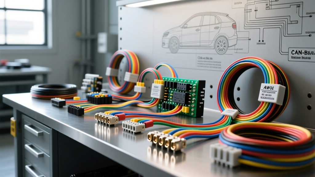
Introduction: Parasitic Draws and Heat-Related Harness Degradation
Modern vehicle electrical architectures are highly complex, relying on multiplexed Controller Area Network (CAN-bus) systems to manage everything from infotainment to powertrain control. When a vehicle sits, modules are designed to enter a 'sleep' state, dropping the parasitic draw to an acceptable baseline of 50mA (0.05A) or less. However, environmental extremes—specifically the intense, prolonged summer heat found in the Southwest—can cause severe insulation degradation. Cross-linked polyethylene (XLPE) and PVC wire coatings can become brittle, melt against exhaust manifolds, or chafe through protective loom tubing, leading to intermittent micro-shorts that keep the Body Control Module (BCM) awake.
While a methodical DIY approach can isolate many parasitic draws using a digital multimeter (DMM), severe network topology faults or heat-baked engine bay harnesses often require advanced oscilloscope diagnostics and dealer-level reflashing. If you are located in the DFW metroplex and encounter multiplexed network failures, seeking specialized auto electric services Plano TX is the most reliable path to resolve deep-level CAN-bus faults and replace degraded OEM harness segments. Below is our comprehensive, step-by-step troubleshooting flow for isolating advanced parasitic draws and network faults.
Phase 1: Baseline Measurement and Module Sleep Protocols
Before pulling a single fuse, you must establish an accurate baseline. Late-model vehicles (especially FCA, GM, and European platforms) require extended sleep cycles. A CAN-bus network operating under ISO 15765-4 standards can take up to 45 minutes to fully power down after the ignition is turned off and the doors are locked.
Step-by-Step Baseline Setup:
- Step 1: Disconnect the negative battery terminal. Connect a fused 10A jumper wire between the negative post and the disconnected cable to maintain module memory and prevent anti-theft lockouts.
- Step 2: Connect your DMM (set to the 10A port) in series with the negative battery cable and the disconnected terminal.
- Step 3: Remove the fused jumper wire, forcing all current through the multimeter.
- Step 4: Close all doors, remove the key, and wait 30-45 minutes. Observe the amperage drop. If the draw stabilizes below 0.050A, your system is healthy. If it remains above 0.100A, proceed to Phase 2.
Phase 2: The Voltage Drop Diagnostic Flow (Fuse-by-Fuse)
Pulling fuses one by one with the circuit live can cause voltage spikes that wake up sleeping modules, leading to false diagnostic conclusions. The industry-standard method, championed by Fluke Automotive Parasitic Drain Guide, is the fuse voltage drop test. By measuring the millivolt (mV) drop across the top two test points of each blade fuse, you can calculate the exact amperage flowing through that specific circuit without disturbing the network.
Fuse Voltage Drop to Amperage Conversion Chart
| Fuse Rating (A) | Measured mV Drop | Approximate Amperage (A) | Diagnostic Action |
|---|---|---|---|
| 10A (Mini/ATO) | 0.15 mV | 0.010A (10mA) | Normal Sleep State |
| 15A (Mini/ATO) | 0.25 mV | 0.035A (35mA) | Acceptable Limit |
| 20A (ATO) | 1.80 mV | 0.350A (350mA) | FAULT: Module Awake |
| 30A (Maxi) | 4.50 mV | 1.200A (1.2A) | CRITICAL: Dead Short |
Note: Resistance values vary slightly by fuse manufacturer (e.g., Littelfuse vs. Bussmann). Always reference the specific mV chart for your fuse brand.
Phase 3: Isolating the CAN-Bus & Multiplexed Networks
If your voltage drop test indicates that a fuse powering a communication module (like the BCM, PCM, or Telematics Hub) is drawing excessive current, you must test the physical network topology. According to AA1Car CAN-Bus Diagnostics, a short in the twisted pair wiring will cause termination resistors to overheat and modules to broadcast endless wake-up commands.
OBD2 Pinout Verification:
Access the Data Link Connector (DLC) under the dashboard. You will be testing the CAN-High and CAN-Low circuits.
- Pin 6 (CAN-High): Typically White or twisted with a colored tracer. Idle voltage should be ~2.6V.
- Pin 14 (CAN-Low): Typically Green or twisted with a colored tracer. Idle voltage should be ~2.4V.
- Pins 4 & 5: Chassis and Signal Grounds.
Termination Resistance Test:
With the battery disconnected, set your DMM to Ohms (Ω). Measure the resistance between Pin 6 and Pin 14. A healthy SAE J1939 / ISO 15765 CAN-bus network will read exactly 60 ohms. This is the result of two 120-ohm termination resistors (usually located in the PCM and the BCM) wired in parallel. If you read 120 ohms, one resistor or module is missing/offline. If you read near 0 ohms, the CAN-H and CAN-L wires are shorted together, often due to melted insulation in the engine bay harness.
Phase 4: Starter Circuit & Alternator Sense Wire Verification
Parasitic draws are not exclusively caused by CAN-bus faults. Degraded heavy-gauge wiring in the starter and alternator circuits can cause massive current leaks and voltage drop issues, especially in high-heat environments.
Alternator Sense Wire (PCM Controlled)
Modern alternators do not use internal voltage regulators; they are controlled by the PCM via a duty-cycle signal or a direct sense wire. The sense wire is typically 18 AWG, often colored Red/White or Gray, routing from the alternator 'S' terminal directly to the PCM. If this 18 AWG wire suffers from heat-induced corrosion at the crimp connector, the PCM reads a false low-voltage state and commands the alternator to maximum output (14.8V+), which boils the battery and causes massive parasitic surface charges that mimic a draw.
Starter Solenoid 'S' Wire
The starter solenoid trigger wire is usually 12 AWG (often Purple or Yellow). Because it is routed near the exhaust headers, the insulation frequently degrades. A micro-short between the 12 AWG S-wire and the engine block will bypass the ignition switch, draining the battery continuously and potentially engaging the starter while the engine is running.
Decision Tree: When to Escalate to Professional Diagnostics
Use the following decision flow to determine if the repair is within your DIY capabilities or if you require professional intervention:
- Symptom: Single module awake (e.g., aftermarket alarm or faulty glovebox switch).
Action: DIY repair. Replace switch or remove aftermarket tap. - Symptom: CAN-bus reads 120 ohms; specific module is offline.
Action: DIY trace. Check power and ground pins at the offline module connector using a wiring diagram. - Symptom: CAN-bus reads <10 ohms; multiple modules throwing U-codes (U0100, U0140).
Action: Professional Escalation. This indicates a severe physical short in the main harness trunk. In extreme heat climates, locating the exact melted node inside a wrapped harness requires thermal imaging and oscilloscope signal tracing. This is the exact scenario where utilizing expert auto electric services Plano TX becomes critical, as they possess the dealer-level schematics, thermal cameras, and module-reflashing tools required to safely replace and reprogram the affected network segments without bricking the vehicle's immobilizer system.
By following this structured troubleshooting flow, you can accurately pinpoint the source of electrical degradation, save hours of diagnostic guesswork, and safely determine when to hand the vehicle over to a specialized automotive electrical technician.