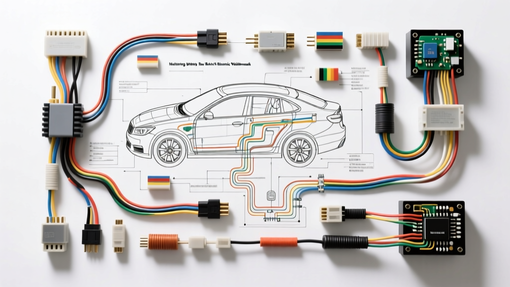
The Philosophy of the Ken's Auto Electric Methodology
When industry veterans reference the Ken's Auto Electric methodology for wiring diagram walkthroughs, they are discussing a systematic, uncompromising approach to schematic interpretation. In modern automotive diagnostics, a wiring diagram is not merely a reference map; it is the definitive topographical guide to a vehicle's nervous system. The 'Ken's Auto Electric' approach mandates that technicians never assume a circuit's physical layout matches its logical flow without empirical verification. This guide will walk you through this rigorous methodology, focusing on tracing complex circuits, interpreting manufacturer-specific symbology, and applying strict voltage drop testing protocols to validate the diagram against real-world vehicle conditions.
Phase 1: Decoding the Schematic Legend and Topography
Before tracing a single wire, the walkthrough begins with a complete audit of the diagram's legend. Different OEMs use varying nomenclature for splices, grounds, and connectors. For instance, General Motors utilizes a strict alphanumeric ground designation system (e.g., G100 series for engine compartment grounds, G200 for instrument panel, G300 for passenger cabin). Ford often designates grounds with a 'G' followed by a three-digit number correlated to the specific harness branch.
The Ken's Auto Electric standard requires identifying three critical elements before touching a multimeter:
- Splice Packs (S-Designations): Locating where a single B+ or ground feed splits into multiple branches. A failure at an S-splice (like S104) will cause cascading, seemingly unrelated electrical faults across multiple modules.
- Connector Cavity Numbers: Understanding that Pin 1 on a diagram may not physically correspond to the top-left cavity on the actual component connector. You must cross-reference the connector face-view chart.
- Wire Color Codes and Tracers: Noting the base color and stripe (tracer). A 'RED/WHT' wire is fundamentally different from a 'WHT/RED' wire in OEM harness manufacturing.
Phase 2: Step-by-Step Walkthrough of the Starter Control Circuit
To demonstrate this methodology, we will perform a complete walkthrough of a modern, PCM-controlled starter circuit (common in late-model GM and FCA vehicles). This circuit moves away from the traditional ignition-switch-direct-to-solenoid design and instead utilizes a localized underhood relay controlled by the Powertrain Control Module (PCM).
Step 1: The Main Battery Feed (High Amperage)
The circuit originates at the battery positive post. A 1/0 AWG (or 2 AWG) primary cable routes directly to the starter motor's main B+ terminal and the underhood fuse block. According to SAE J1128 standards, a 1/0 AWG wire is required to handle the 150-250 amp inrush current of the starter motor without excessive voltage drop or thermal degradation. This portion of the diagram is typically represented by a heavy, bold line, often bypassing standard fuse blocks in favor of a mega-fuse or fusible link rated at 175A to 250A.
Step 2: The Ignition Switch Signal (Low Amperage)
When the driver turns the key to 'CRANK' (or presses the start button), the Body Control Module (BCM) or ignition switch sends a 12V B+ signal. This is typically an 18 AWG or 16 AWG Yellow or Pink wire. In the diagram walkthrough, we trace this wire not to the starter, but to the PCM or the Coil side of the Starter Relay (Pin 86). The Ken's Auto Electric method emphasizes checking for the presence of this 12V signal at the relay socket before moving downstream.
Step 3: The PCM Interlock and Ground Control
Modern diagrams show the PCM completing the relay's control circuit. The PCM monitors the Transmission Range Sensor (PRNDL) to ensure the vehicle is in Park or Neutral. If conditions are met, the PCM internally grounds the relay control circuit (Pin 85). This ground path is usually an 18 AWG Black or Black/White wire. If the starter fails to crank, the diagram dictates we must scan the PCM for PRNDL agreement before condemning the starter.
Step 4: The Relay Load Circuit to the Solenoid
Once the relay coil is energized, the internal switch closes, connecting Pin 30 (Constant B+) to Pin 87 (Load Out). The output wire routing from Pin 87 to the starter solenoid's 'S' terminal is traditionally a 14 AWG or 12 AWG Purple wire (in GM applications) or Red/Light Blue (in older Ford applications). This wire carries roughly 3 to 5 amps to pull in the starter solenoid plunger, which in turn bridges the massive internal copper contacts for the motor.
Reference Chart: ISO Mini Relay Pinout and Diagnostic Values
A core component of any wiring diagram walkthrough is understanding the standardized ISO mini-relay. Below is the diagnostic reference table used to verify relay socket integrity during a no-crank condition.
| Relay Pin | Function | Wire Size (Typical) | Expected DMM Reading (Key in Crank) | Common Failure Mode |
|---|---|---|---|---|
| 30 | Constant B+ Feed (Source) | 12 AWG - 10 AWG | Battery Voltage (12.2V - 12.6V) | Blown mega-fuse, corroded underhood fuse block terminal. |
| 87 | Load Output (To Solenoid) | 14 AWG - 12 AWG | Battery Voltage (when relay energized) | High resistance in purple wire, broken S-terminal spade. |
| 86 | Coil B+ Feed (Ignition/BCM) | 18 AWG - 16 AWG | Battery Voltage (11.5V+ during crank) | Ignition switch failure, broken wire in steering column boot. |
| 85 | Coil Ground (PCM Controlled) | 18 AWG | Less than 0.1V drop to chassis ground | PCM driver failure, PRNDL mismatch, open ground splice. |
Phase 3: The Voltage Drop Verification Protocol
A wiring diagram only shows logical connectivity; it does not reveal hidden resistance. The hallmark of the Ken's Auto Electric walkthrough is the mandatory use of voltage drop testing to verify the physical health of the circuit mapped out in the diagram. Using a high-impedance Digital Multimeter (DMM) set to DC Millivolts (mV), technicians measure the potential difference across connections while the circuit is under load.
Strict adherence to these thresholds is required:
- Individual Connections (Terminals, Splices, Switches): Maximum allowable voltage drop is 100 mV (0.10V).
- Total Wire Runs (Cable lengths): Maximum allowable drop is 20 mV (0.02V) per foot of heavy gauge cable.
- Total Ground Circuit: Maximum allowable drop from the component housing to the battery negative post is 100 mV (0.10V).
- Total Positive Circuit: Maximum allowable drop from the battery positive post to the component B+ terminal is 500 mV (0.50V) for standard accessory circuits, and 200 mV (0.20V) for high-amperage starter circuits.
If your diagram indicates a continuous path from the battery to the starter solenoid, but your voltage drop test across the underhood fuse block busbar reads 1.2V, you have found the fault. The diagram showed a connection, but the physical reality is severe galvanic corrosion or a loose terminal crimp.
Advanced Troubleshooting: Ground Topography and TPA Locks
The final phase of the walkthrough involves inspecting the physical termination points identified in the diagram's ground matrix. A schematic might show G104 located 'Left Front Fender Inner Panel'. In reality, this ground point is highly susceptible to water intrusion, road salt, and dissimilar metal corrosion. When testing a circuit that the diagram shows as complete, always back-probe the connector rather than piercing the wire insulation. Piercing wires compromises the dielectric seal and invites capillary action, drawing moisture into the copper strands and creating future ASE-documented parasitic draws or high-resistance faults.
Furthermore, verify the Terminal Position Assurance (TPA) locks. A wiring diagram will not indicate if a terminal has backed out of its connector cavity due to a missing or broken TPA lock. If Pin 87 shows continuity on the bench but fails under the vibration of engine cranking, a backed-out terminal is the prime suspect. The Ken's Auto Electric methodology teaches that the diagram is the law, but the physical connector is the reality. Mastering the space between the two is the essence of elite automotive electrical diagnostics.